Clip

Inactive Publication Date: 2010-12-02
PIOLAX CO LTD
View PDF16 Cites 17 Cited by
  • Summary
  • Abstract
  • Description
  • Claims
  • Application Information

AI Technical Summary

Benefits of technology

[0012]One of objects of the present invention is to provide a clip capable of being simply formed and being tightly engaged with a mounting hole regardless of a plate thickness of the mounting subject in which the mounting hole is formed.

Problems solved by technology

In the clip of JP-3120355-B, a slit is required at the shaft portion and enlarged head portion of the base in order to assemble the spring body with the base, and thus, the structure of the base is complicated.
As a result, since an expanding amount at the stopper portion side of the spring body is insufficient, it is not suitably applicable to the mount-base member having thin plate thickness, and backlash may arise in some cases.
Further, since the spring portion engaged with the back side of the mounting hole is formed by folding back each side of the clip outside, the structure of the clip is complicated, and there is a problem in terms of productivity.

Method used


Image

  • Clip
  • Clip
  • Clip

Examples


Example

[0032]Hereinafter, embodiments of the present invention will be described with reference to FIGS. 1 to 5B.

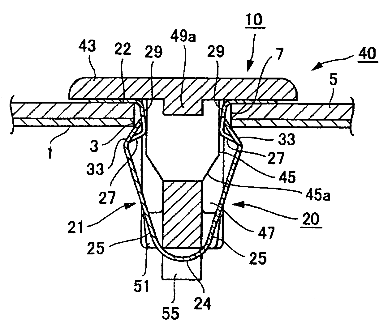
[0033]As shown in FIG. 5B, for example, a clip 10 according to an embodiment is inserted into and fixed with a mounting hole 3 formed in a mount-base member 1 such as a body panel. For example, a mounting-subject member 5 such as a trim board, a panel member, a garnish, a cover, an assist grip is mounted to the mount-base member 1 through the clip 10.

[0034]As shown in FIG. 1, the clip 10 includes a plate spring member 20 and a pin member 40 assembled with the plate spring member 20.

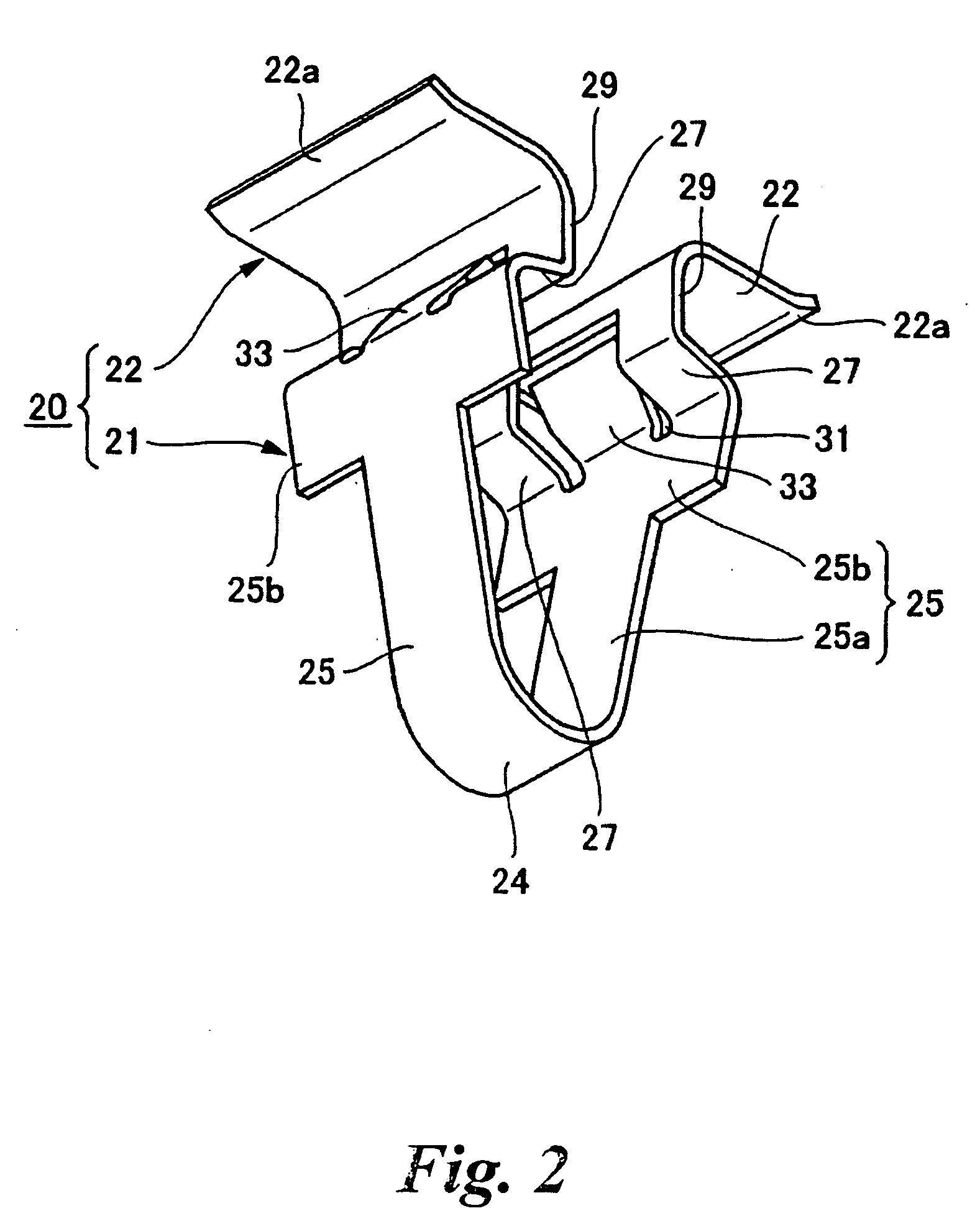
[0035]First, the plate spring member 20 will be described with reference to FIG. 2 and FIGS. 4A and 4B. The plate spring member 20 is formed from a metal plate. The plate spring member 20 includes a leg portion 21 and flange portions 22. The leg portion 21 is bent into a V-shape so as to sandwich the shaft portion of the pin member 40 as described later, and the flange portions 22 outwardly extend from b


PUM


Abstract

According to embodiments of the present invention, a clip includes: a plate spring member having a leg portion and flange portions; a pin member having a shaft portion and a head portion. The leg portion has: inclined portions outwardly extending from a bent portion; engagement portions inwardly extending from the inclined portions; and abutting portions connected between the inclined portions and the flange portions. The shaft portion has: a proximal-side diameter-expanded portion; and a distal-side diameter-reduced portion. When the plate spring member is assembled with the pin member and flange portions abut a front side circumference of the mounting hole, the diameter-expanded portion abut the abutting portions to expand the leg portion through a further pushing operation of the pin member thereby engaging the engagement portions with a back side circumference of the mounting hole.

Description


Claims


Application Information

Patent Timeline
Owner PIOLAX CO LTD
Why Eureka
Try Eureka