Three part tube

Inactive Publication Date: 2010-12-09
AB ELECTROLUX
View PDF3 Cites 14 Cited by
  • Summary
  • Abstract
  • Description
  • Claims
  • Application Information

AI Technical Summary

Benefits of technology

[0016]In accordance with an embodiment of the telescopic tube for a vacuum cleaner as defined in claim 8, the outer tube has a larger diameter than the first inner tube and the second inner tube, and the second inner tube has a larger diameter than the first inner tube. Thus, the first inner tube can be retracted into the second inner tube, which in turn can be retracted into the outer tube. This allows for achieving a reduced length of the telescopic tube in the fully retracted position. Thus, valuable space can be saved when storing the tube.
[0017]In accordance with an embodiment of the telescopic tube for a vacuum cleaner as defined in claim 9, the position of the inner tubes relative to the outer tube is continuously adjustable, thus making it possible for the user to make a precise adjustment of the length to fit to his or her own height or to some other required criteria, like for instance required radial range of the vacuum cleaner tube.

Problems solved by technology

A problem with this known three-part telescopic tube is that the adjusting the length of the tube by operating the telescopic links can be experienced as troublesome.

Method used


Image

  • Three part tube
  • Three part tube
  • Three part tube

Examples


Example

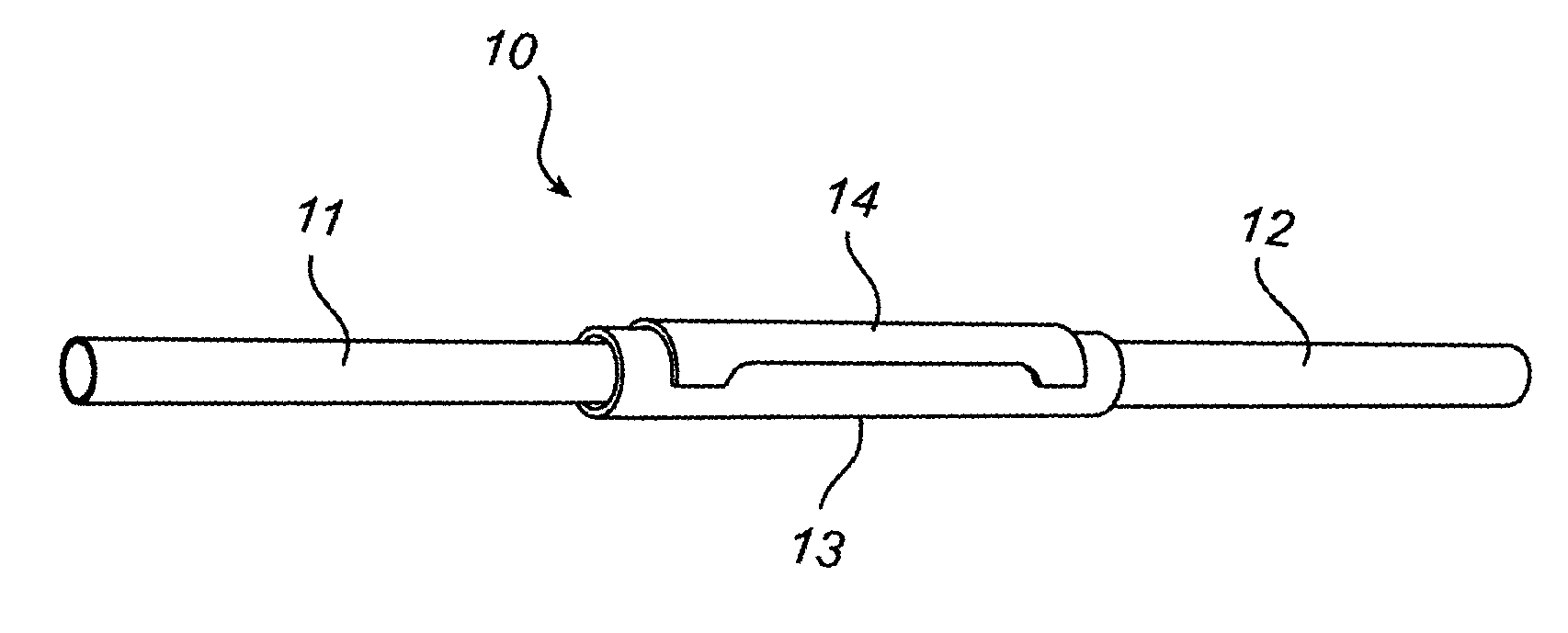
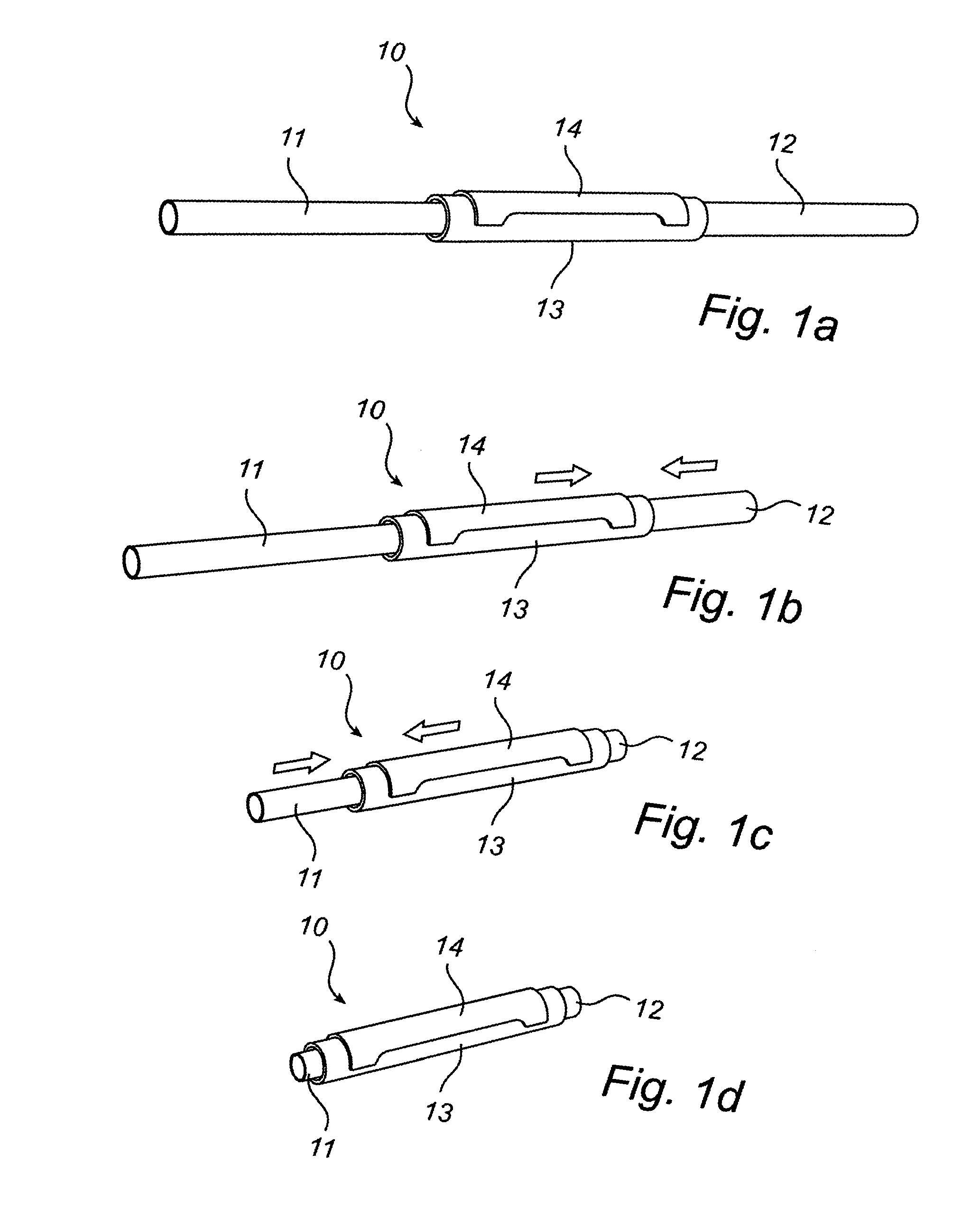
[0028]Referring to FIG. 1a), there is shown a schematic drawing of a telescopic tube for a vacuum cleaner 10 according an embodiment of the present invention. The telescopic tube 10 comprises a first inner tube 11, herein after referred to as the lower tube 11, a second inner tube 12, herein after referred to as the upper tube 12, and an outer tube 13. The upper tube 12 is arranged to be longitudinally movable inside the outer tube 13, while the lower tube 11 is arranged to be longitudinally movable inside the upper tube 12 and the outer tube 13. Hence, the outer tube 13 can encompass at least a portion of the upper tube 12 and at least a portion of the lower tube 11. In this embodiment the outer tube 13 is of about the same length as, but somewhat shorter than, the lower tube 11 and upper tube 12. Hence, the outer tube 13 contributes to a substantial part of the fully extended telescopic tube 10, while at the same time allowing the inner tubes, 11 and 12, to be almost fully retracted


PUM


Abstract

This invention relates to a telescopic vacuum cleaner tube comprising a first inner tube, a second inner tube, and an outer tube, wherein the first and second inner tubes are arranged to form first and second telescopic links relative to first and second end portions of the outer tube, respectively. The outer tube forms the intermediate tube of the three-part tube while at the same time being fully accessible in any position, whereby one common grip for operating both of the two respective telescopic links, formed by the first and second inner tubes and the intermediate outer tube, of the three part telescopic tube is obtained.

Description


Claims


Application Information

Patent Timeline
Owner AB ELECTROLUX
Why Eureka
Try Eureka