Method for repairing a sealing segment of a gas turbine

Inactive Publication Date: 2011-01-06
MTU AERO ENGINES GMBH
View PDF3 Cites 10 Cited by
  • Summary
  • Abstract
  • Description
  • Claims
  • Application Information

AI Technical Summary

Problems solved by technology

Maintaining a minimal gap between the rotating rotor blades and the fixed casing of a high-pressure turbine is especially problematic in the context of aircraft engines.
In high-pressure turbines, the task of maintaining the gap is complicated by the extremely high temperatures and temperature gradients occurring therein.
Since the frictional contact of the blade tips causes material to be ablated from said tips and from the sealing segments, the gap can become undesirably enlarged over the entire periphery of the casing and rotor.
Consequently, the sealing segments are subject to wear.
Other types of damage mechanisms that may occur include thermomechanical fatigue and local overheating, resulting in cracks and burned areas.
When larger or more dramatic damage has occurred to a sealing segment or shroud, such sealing segment or shroud cannot be repaired, bust must be completely replaced.

Method used


Image

  • Method for repairing a sealing segment of a gas turbine
  • Method for repairing a sealing segment of a gas turbine

Examples


Example

[0016]One embodiment of the present invention will now described in more detail with reference to FIG. 1.

[0017]This embodiment of the present invention is directed to a method for repairing or reconditioning sealing segments secured to the casing of a gas turbine.

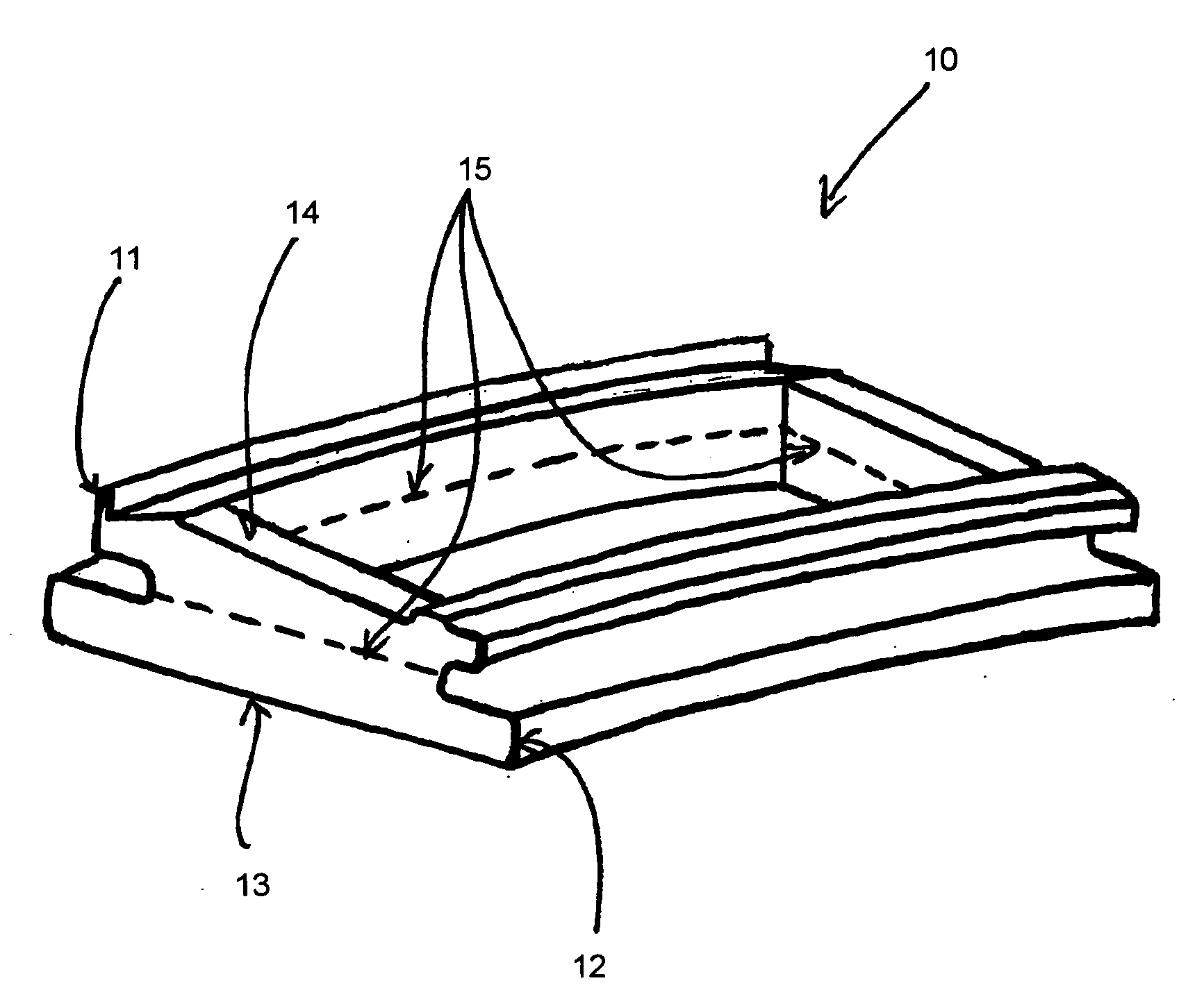
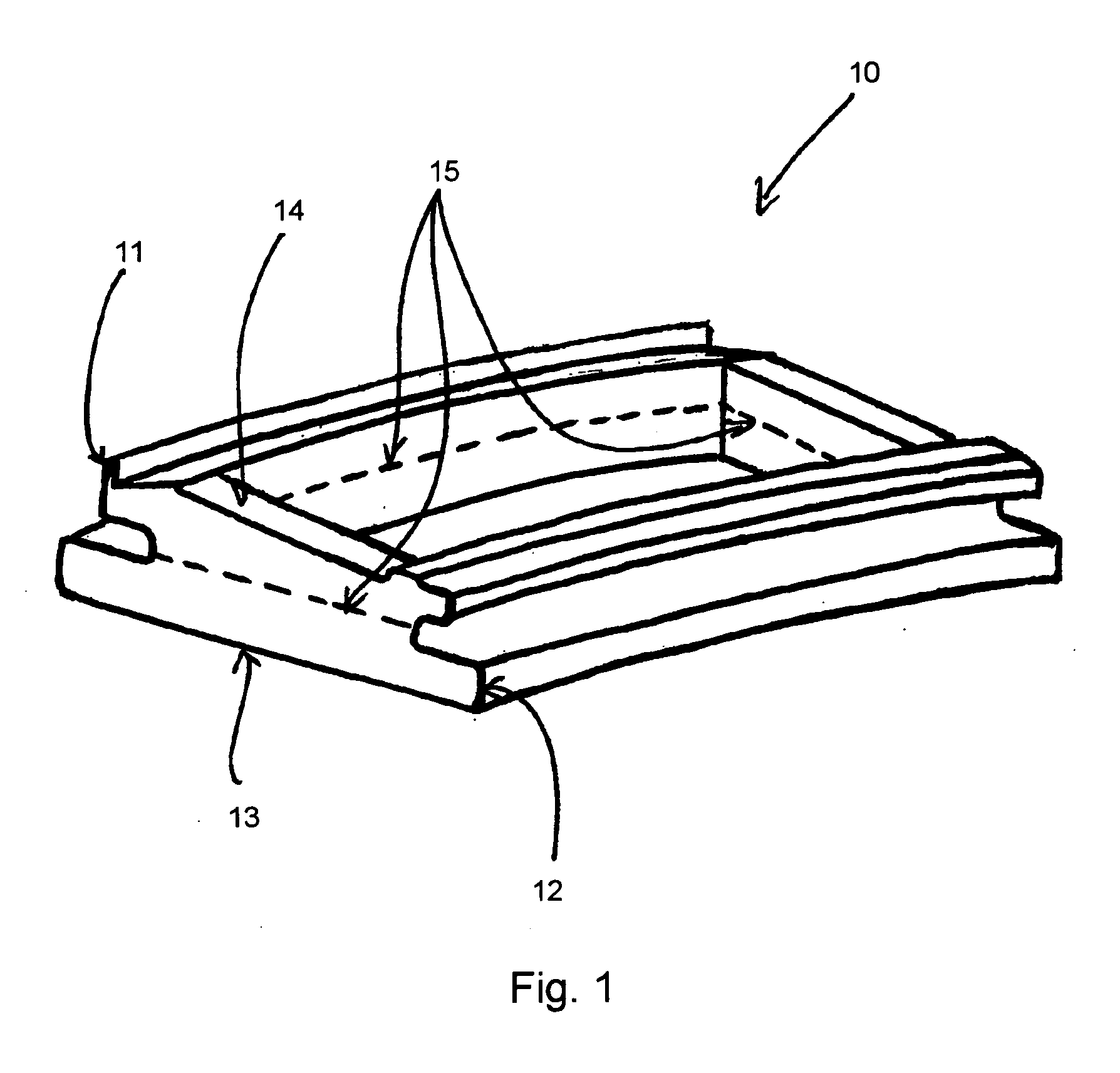
[0018]FIG. 1 shows a sealing segment 10 of a gas turbine in a schematic perspective view. Sealing segment 10 includes a radially outer, frame-like holding portion 11 for a radially inner abradable portion 12. Via holding portion 11, a sealing segment 10 can be secured to a stator casing of the gas turbine.

[0019]Radially inner abradable portion 12 provides an abradable coating for contact with the tips of rotating rotor blades. Sealing segment 10 typically has a continuous closed surface 13 in the region of radially inner abradable portion 12, whereas in the region of radially outer frame-like holding portion 11, sealing segment 10 has a surface 14 which is not closed.

[0020]When such a sealing segment 10 is damaged and is to be


PUM


Abstract

A method for repairing a sealing segment of a gas turbine is provided. The sealing segment includes a radially outer holding portion for a radially inner abradable portion. The method includes the steps of providing a sealing segment to be repaired; removing a damaged, radially inner abradable portion of the sealing segment along a circumferentially extending parting plane, such that the abradable portion is completely removed from the holding portion; making a replacement part for the separated abradable portion of the sealing segment; and joining the replacement part to the holding portion of the sealing segment.

Description


Claims


Application Information

Patent Timeline
Owner MTU AERO ENGINES GMBH
Why Eureka
Try Eureka