Medical implantable lead and method for connecting a medical implantable lead to an organ
a technology of medical implants and lead leads, applied in the field of medical implants, can solve the problems of limiting the battery life of electronic devices, deteriorating electrical contact, and not ensuring good electrical conta
- Summary
- Abstract
- Description
- Claims
- Application Information
AI Technical Summary
Benefits of technology
Problems solved by technology
Method used
Image

Examples
first embodiment
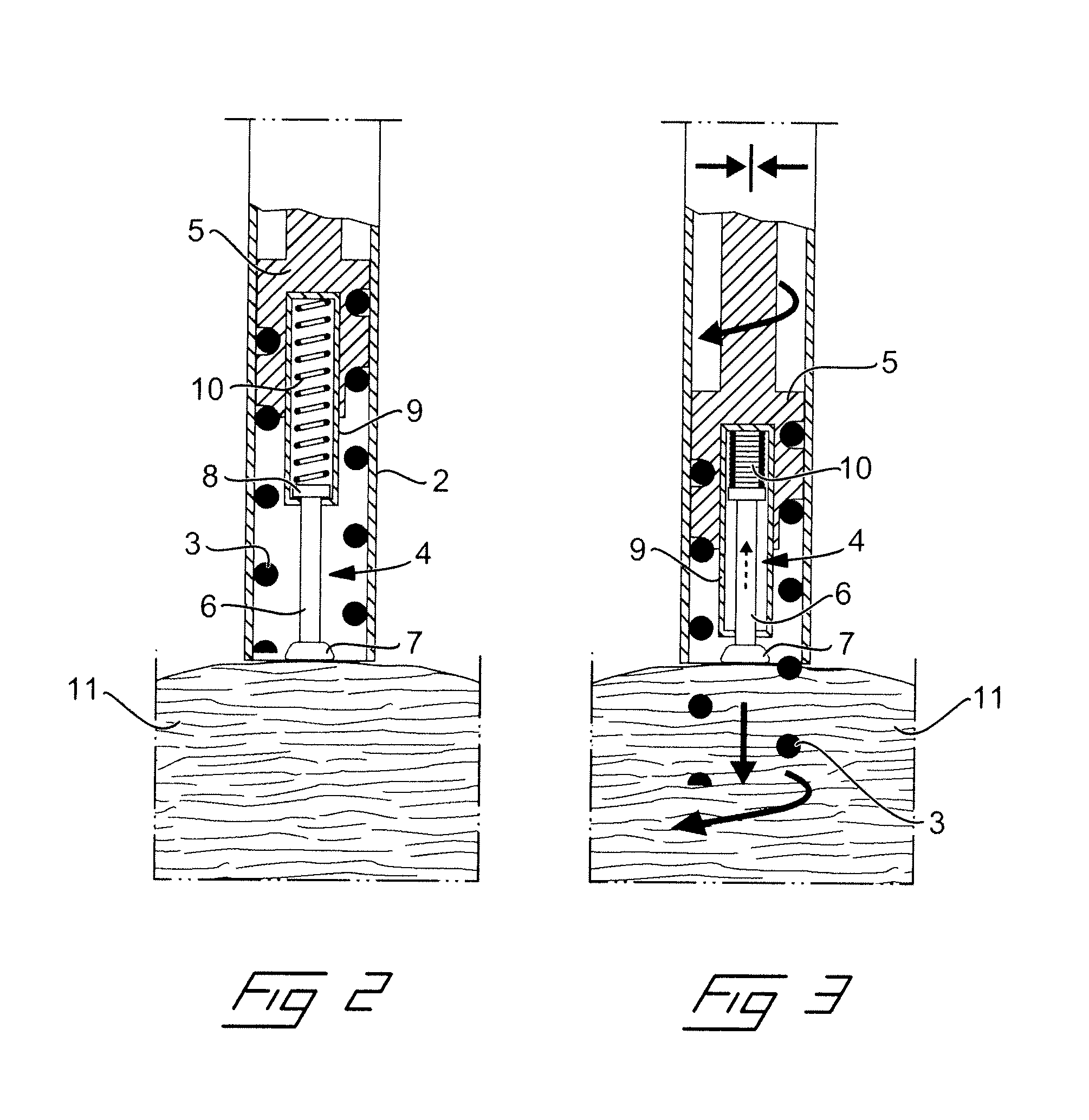
[0032]Next, reference is made to FIGS. 2 and 3 for describing the invention. Inside the header 2 the lead is provided with a helix 3 and an electrode pin 4. The helix 3 as well as the electrode pin 4 is mounted in a coupling 5 such that they project forward towards the distal end of the lead from the coupling. More precisely, the helix 3 is mounted on the outside of the coupling, whereas the electrode pin 4 is mounted in the central of the coupling and positioned within the helix. Moreover, the electrode pin is formed with an elongated shaft 6, a head 7 having an electrode surface in a distal end and a stop member 8 in a proximal end. The stop member 8 is positioned inside a spring housing 9 such that the elongated shaft 6 projects displaceable from a forward opening in the spring housing. A spring 10 inside the spring housing actuates the electrode pin 4 to be displaced in the direction forward towards the distal end of the lead by acting between the proximal end of the spring housing
third embodiment
[0035]A fourth embodiment according to FIGS. 8-10 is similar to the third embodiment according to FIGS. 6 and 7, in that it is provided with an electrode sleeve 12 being displaceable against the action of a spring 14 in a slot 13 in the header 2. However, here this feature is combined with a rotatable and displaceable coupling 5. When attaching the lead to the tissue, this is made possible by a combination of displacing of the electrode sleeve 12, as illustrated in FIG. 9, and rotation and displacing of the coupling 5 and the helix 3 towards the distal end, as illustrated in FIG. 10. One advantage with this embodiment is that the electrode sleeve can be made shorter and with a shorter length of stroke.
fifth embodiment
[0036]A fifth embodiment is illustrated in FIGS. 11 and 12. In this embodiment the electrode itself is formed as a helical spring 15, which is provided with a disc 16 in its distal end for forming of a electrode surface with a sufficient area. The electrode spring 15 is arranged centrally within the helix 3 and the helix as well as the electrode spring is mounted on a rotatable as well as displaceable coupling 5. When connecting the distal end of the lead to the tissue 11, as illustrated in FIG. 12, the coupling is rotated by a not shown rotary means from the proximal end, such that the coupling together with the helix and the electrode spring will be displaced forward towards the distal end of the lead. Accordingly, the helix 3 will penetrate and be screwed into the tissue, whereas the electrode spring 15 will abut with its distal disc 16 against the tissue and be compressed.
PUM
 Abstract
Description
Claims
Application Information
 - R&D Engineer
- R&D Manager
- IP Professional
- Industry Leading Data Capabilities
- Powerful AI technology
- Patent DNA Extraction
Browse by: Latest US Patents, China's latest patents, Technical Efficacy Thesaurus, Application Domain, Technology Topic.
© 2024 PatSnap. All rights reserved.Legal|Privacy policy|Modern Slavery Act Transparency Statement|Sitemap