Phase change memory synaptronic circuit for spiking computation, association and recall

Inactive Publication Date: 2012-04-05
IBM CORP
View PDF40 Cites 95 Cited by
  • Summary
  • Abstract
  • Description
  • Claims
  • Application Information

AI Technical Summary

Benefits of technology

[0006]Embodiments of the invention provide an architecture and method to realize an electronic implementation of spiking neurons interacting with each other via programmable, plastic synapses for computation, and pattern matching tasks such as association and recall. An aspect of the invention includes a method for producing spike-timing dependent plasticity using electronic neurons. In response to an electronic neuron spiking, a spiking signal is sent from the electronic neuron to each driver circuit connected to the axon and dendrite wires (calle

Problems solved by technology

Neuromorphic systems do not generally utilize the t

Method used


Image

  • Phase change memory synaptronic circuit for spiking computation, association and recall
  • Phase change memory synaptronic circuit for spiking computation, association and recall
  • Phase change memory synaptronic circuit for spiking computation, association and recall

Examples


Embodiment Construction

[0020]Embodiments of the invention provide neuromorphic systems, including Phase Change Memory (PCM) synaptronic circuits for spiking computation, association and recall. In one embodiment, the present invention provides a synaptronic circuit architecture and operating method.

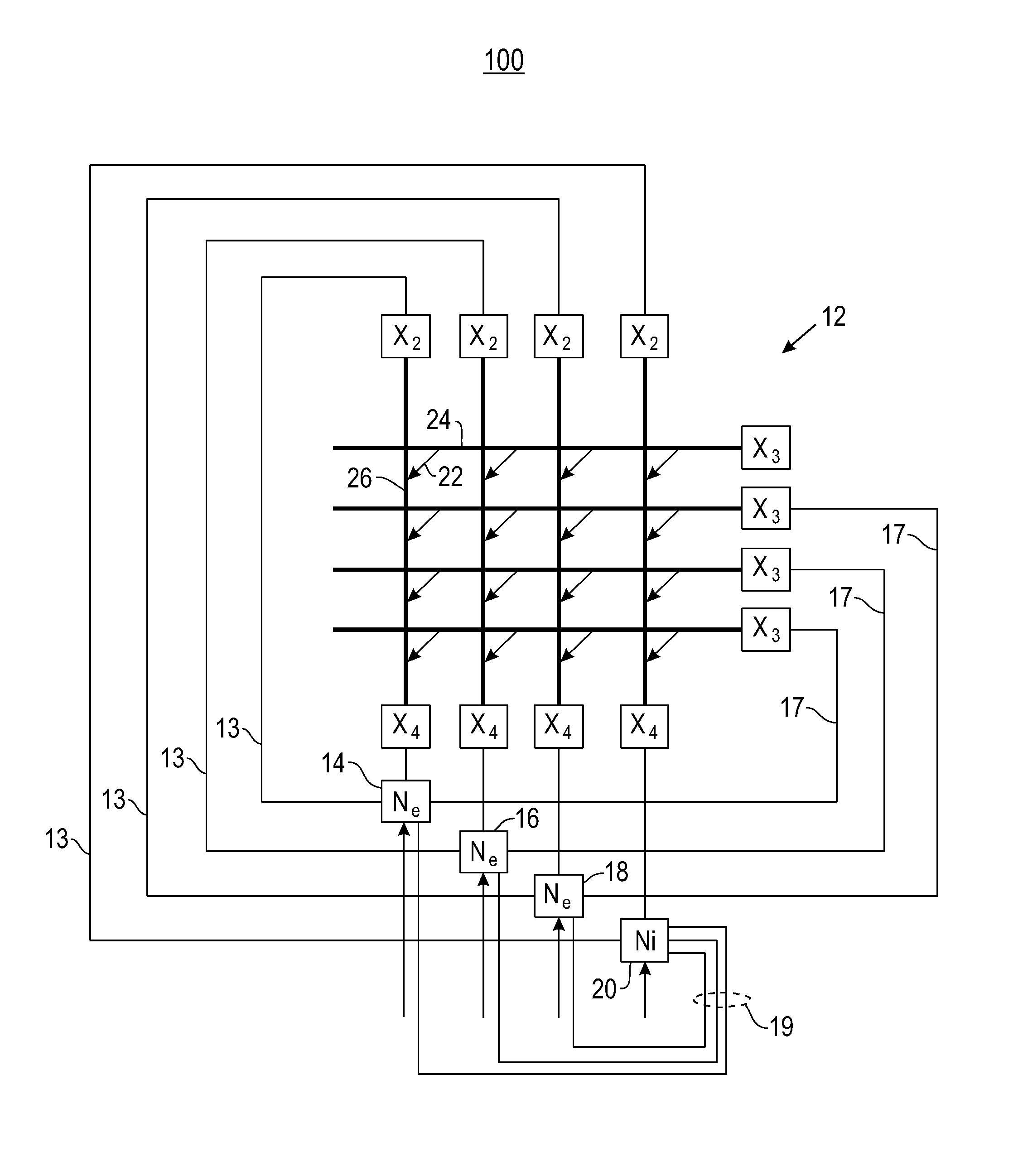
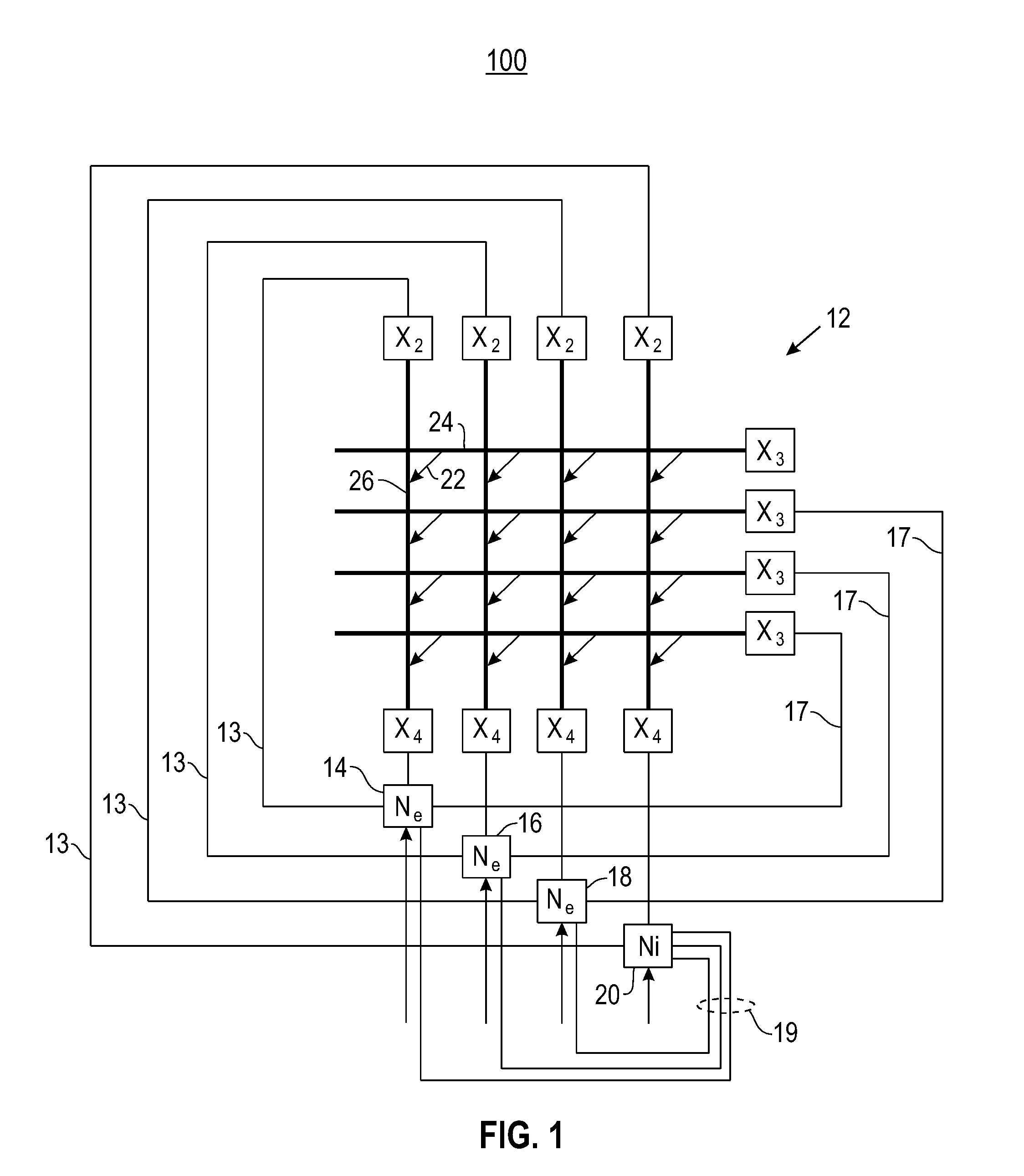
[0021]In one embodiment, the synaptronic circuit comprises a synapse cross-bar array which implements spike-timing dependent plasticity (STDP) using PCM synapse devices. Embodiments include analog variable state resistor which implement amplitude modulated STDP versions and binary variable state resistor which implement probability modulated STDP versions. Disclosed embodiments include systems with access devices and systems without access devices. Referring now to FIG. 1, there is shown a diagram of a neuromorphic system 100 comprising a cross-bar array 12 having a plurality of neurons 14, 16, 18 and 20 as a network. These neurons are also referred to herein as “electronic neurons.” In one example, the cross-bar


PUM


Abstract

Embodiments of the invention are directed to producing spike-timing dependent plasticity using electronic neurons for computation, and pattern matching tasks such as association and recall. In response to an electronic neuron spiking, a spiking signal is sent from the electronic neuron to each axon driver and each dendrite driver connected to the spiking electronic neuron. Each axon driver receiving the spiking signal sends an axonal signal from the axon driver to a variable state resistor. Each dendrite driver receiving the spiking signal sends a dendritic signal from the dendrite driver to the variable state resistor, wherein the variable state resistor couples the axon driver and the dendrite driver. The combination of the axonal and dendritic signals is capable of increasing or decreasing conductance of the variable state resistor.

Description


Claims


Application Information

Patent Timeline
Owner IBM CORP
Why Eureka
Try Eureka