Upper ball joint assembly

a ball joint and assembly technology, applied in the direction of pivotal connections, couplings, mechanical devices, etc., can solve the problems of compromising the integrity of the ball joint, increasing the compressive stress of the conventional ball joint, and often requiring ball joint replacemen

Inactive Publication Date: 2012-04-19
CARLI SUSPENSION
View PDF17 Cites 4 Cited by
  • Summary
  • Abstract
  • Description
  • Claims
  • Application Information

AI Technical Summary

Benefits of technology

This patented describes how different materials can used together during construction or maintenance operations on equipment such as vehicles that use balls. These components are designed differently due to their specific functions they perform well but it should also have certain features like strengths, durability, etc., which makes them difficult to repair once damaged without replacing all these parts altogether. To address this issue, there was developed a new design called the Ball Joint Cup Assembly described earlier in detail below.

Problems solved by technology

This patented technical problem addressed in this patents relates to improving the durability and reliance for controllers used in vehicles like cars when replacing damaged parts after they have gone through regular maintenance cycles over many decades without losing its effectiveness.

Method used


Image

  • Upper ball joint assembly
  • Upper ball joint assembly
  • Upper ball joint assembly

Examples


Embodiment Construction

[0017]The following detailed description is of the best currently contemplated modes of carrying out the invention. The description is not to be taken in a limiting sense, but is made merely for the purpose of illustrating the general principles of the invention.

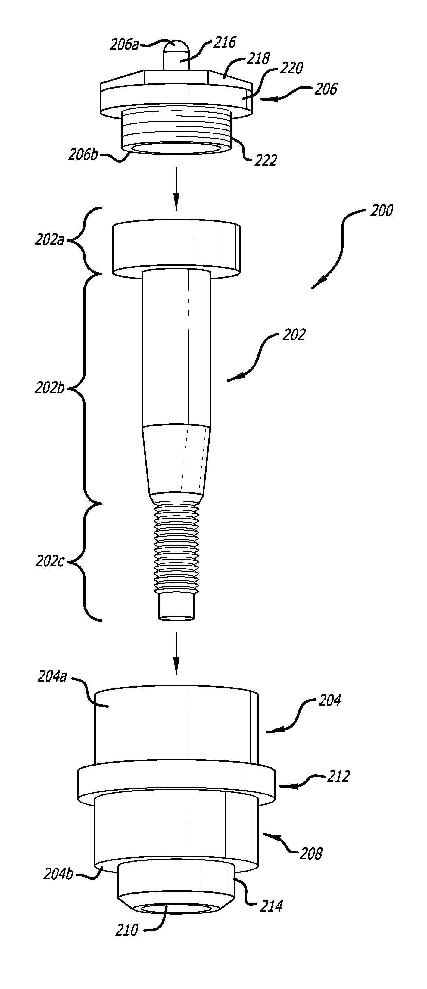
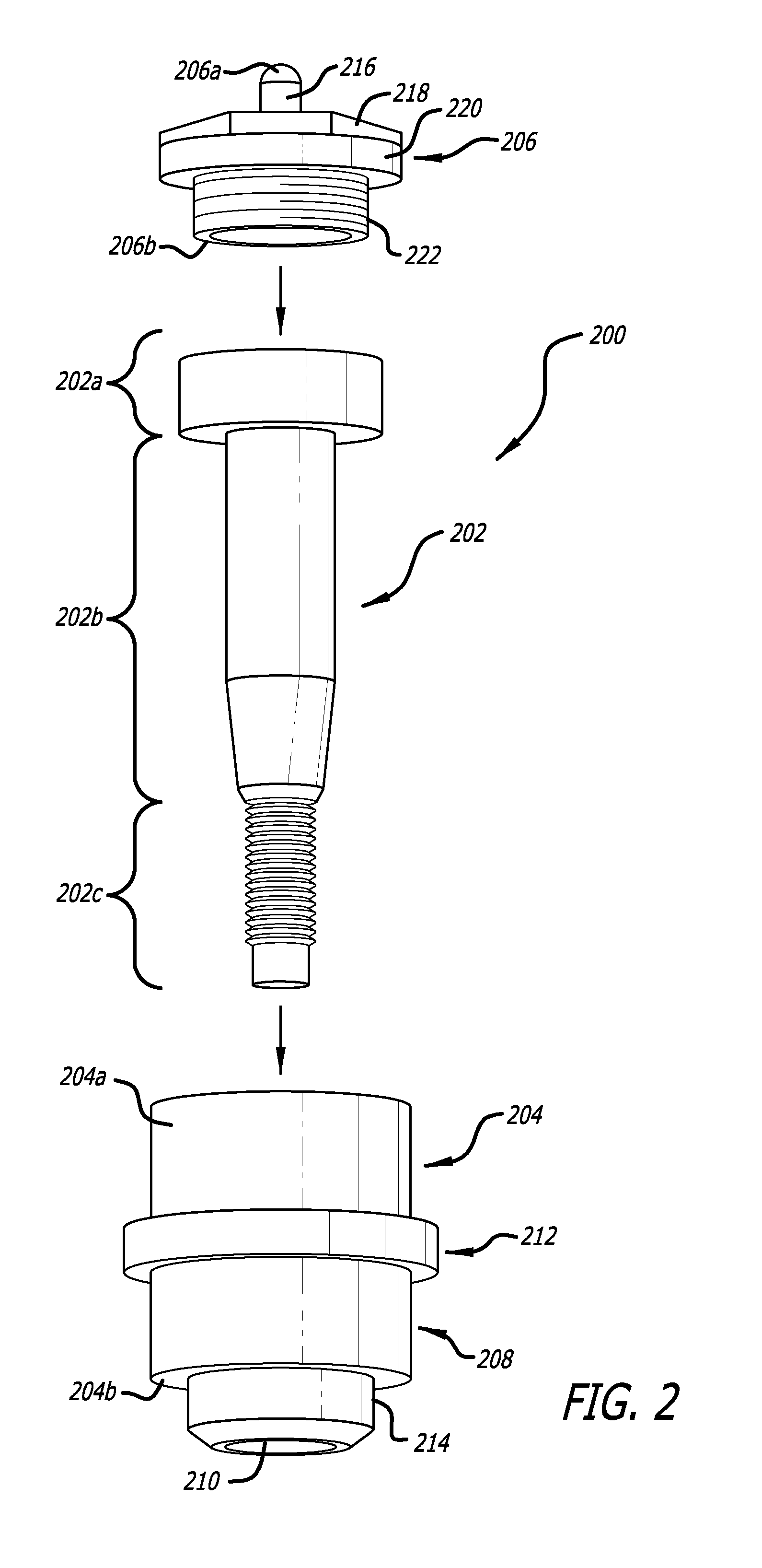
[0018]Embodiments of the invention are directed to an upper ball joint assembly for connecting an upper axle housing to a steering knuckle of a vehicle. In one embodiment, the upper ball joint assembly comprises a plurality of components including a tapered ball joint pin (or stud), a ball joint cup and a threaded cap configured to assemble together into an upper ball joint assembly. In an assembled configuration, a proximal, or head component, of the ball joint pin may be housed within one or more chambers (or tiers) of the ball joint cup. The cap may reversibly engage with the ball joint cup to complete the assembly. The ball joint assembly may have a hardness characteristic of between forty (40) and one-hundred (100) Rockwel


PUM

PropertyMeasurementUnit
Diameteraaaaaaaaaa
Strengthaaaaaaaaaa
Hardnessaaaaaaaaaa

Abstract

Embodiments of the invention are directed to an upper ball joint assembly for connecting an upper axle housing to a steering knuckle of a vehicle. In one embodiment, the upper ball joint assembly comprises a plurality of components including a tapered ball joint pin (or stud), a ball joint cup and a threaded cap configured to assemble together into an upper ball joint assembly. In an assembled configuration, a proximal, or head component, of the ball joint pin may be housed within one or more chambers (or tiers) of the ball joint cup. The cap may reversibly engage with the ball joint cup to complete the assembly. The ball joint assembly may have a hardness characteristic of between forty (40) and one-hundred (100) Rockwell.

Description


Claims


Application Information

Patent Timeline
Owner CARLI SUSPENSION
Why Eureka
Try Eureka