Method and system for providing interface compatibility between devices in system

a technology of interface compatibility and video surveillance system, which is applied in the field of video surveillance system, can solve the problems of inability to interoperate with the security devices having the unique interface of the respective manufacturers in the existing video surveillance system, and the inability to perform interworking operations between the security devices developed by different manufacturers,

Inactive Publication Date: 2012-06-14
ELECTRONICS & TELECOMM RES INST
View PDF3 Cites 1 Cited by
  • Summary
  • Abstract
  • Description
  • Claims
  • Application Information

AI Technical Summary

Benefits of technology

The technical effect of this patented invention is that it allows security cameras with different interfaces to work together more efficiently without compromising their ability to protect sensitive data from being captured by other systems or unauthorized access.

Problems solved by technology

The technical problem addressed in this patent text relates to the lack of compatibility between security devices used in current systems due to differences in hardware or software interfaces among various vendors' products. This can make replacing these security devices more challenging than necessary.

Method used


Image

  • Method and system for providing interface compatibility between devices in system
  • Method and system for providing interface compatibility between devices in system
  • Method and system for providing interface compatibility between devices in system

Examples


Embodiment Construction

[0037]Hereinafter, embodiments of the present invention will be described in detail with reference to the accompanying drawings so that they can be readily implemented by those skilled in the art.

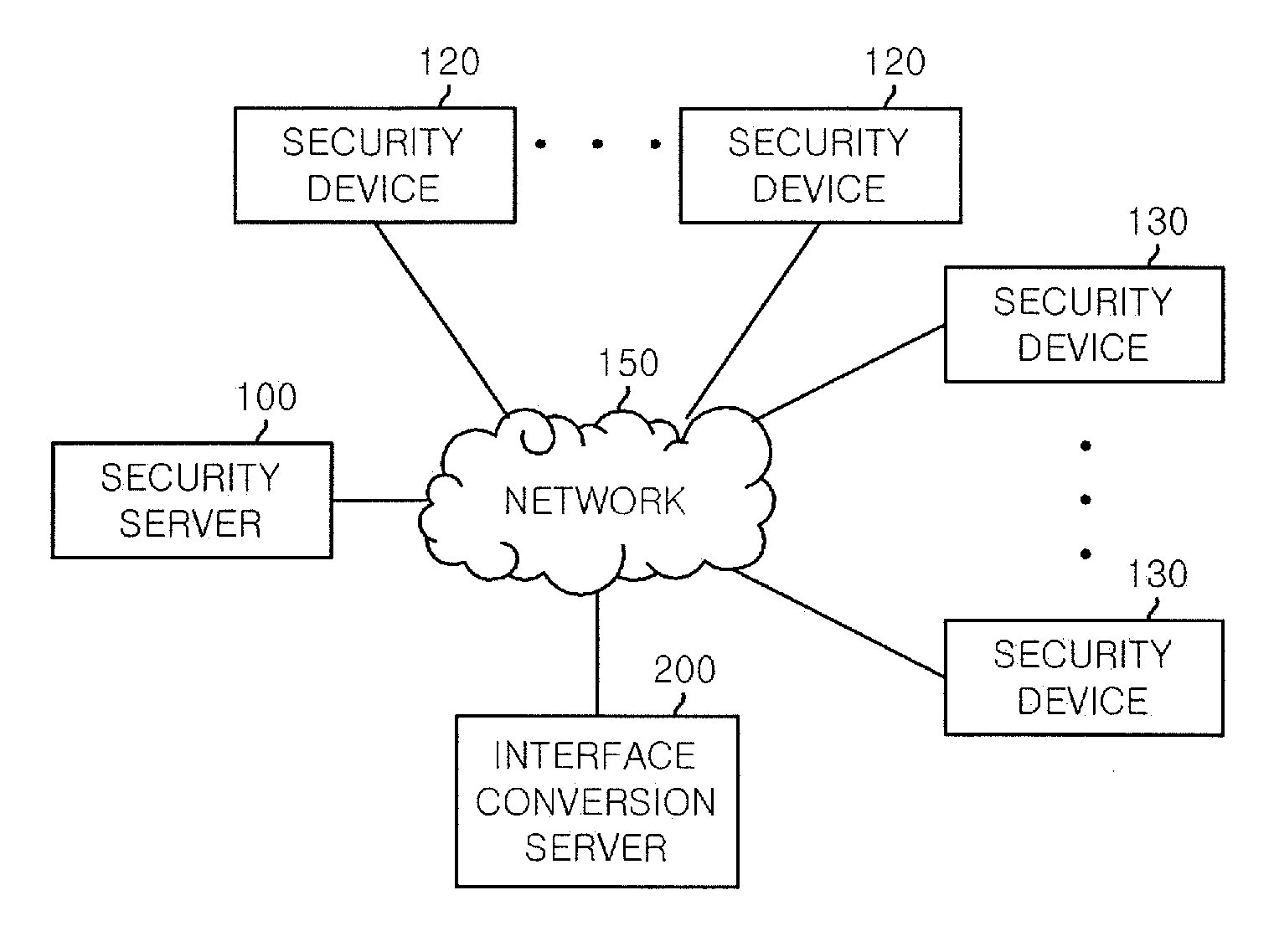
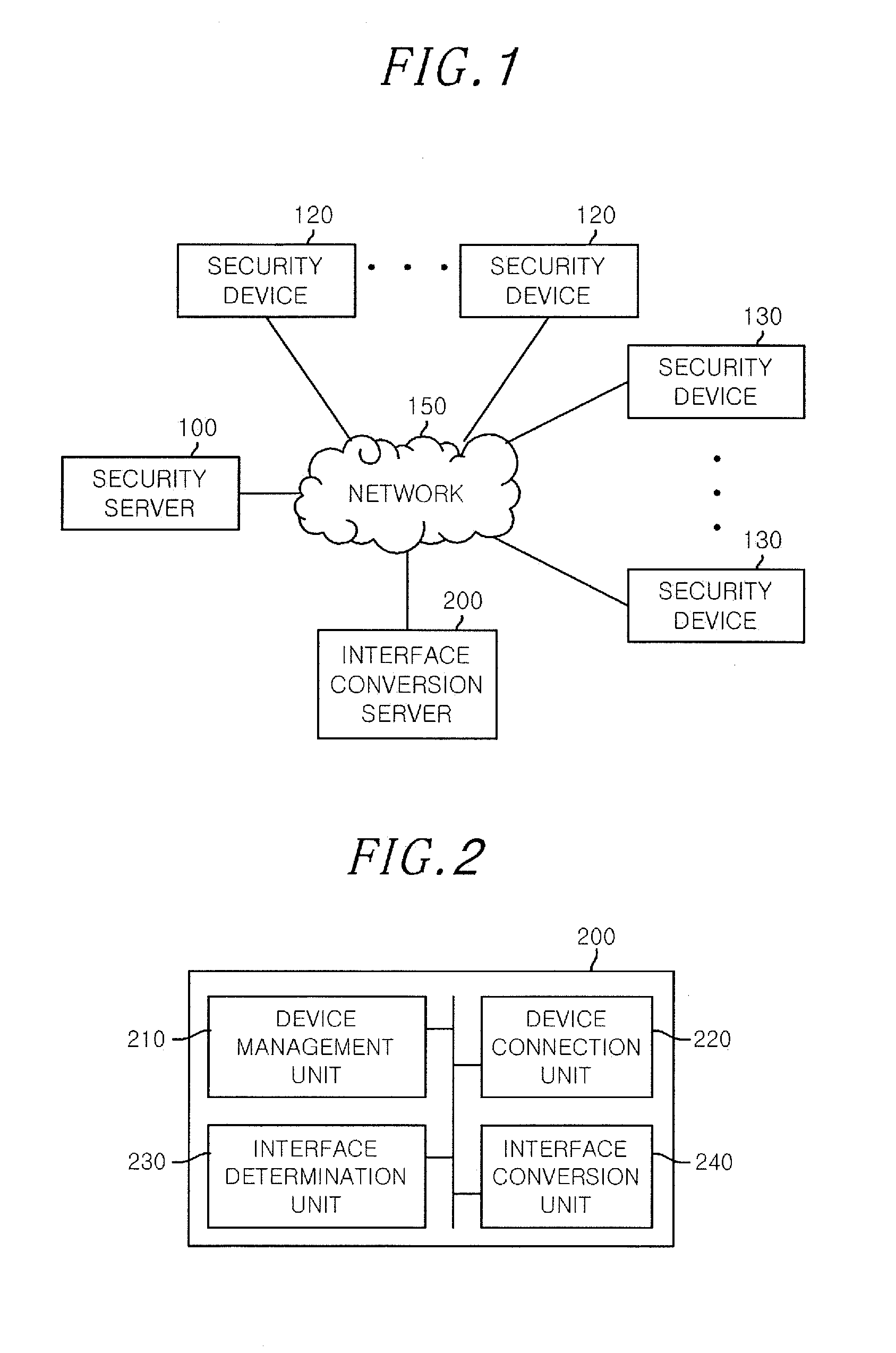
[0038]FIG. 1 is a block diagram of a video surveillance system in accordance with an embodiment of the present invention.

[0039]The video surveillance system includes a plurality of security devices 120 and 130, a security server 100, and an interface conversion server 200, all of which are connected to an IP-based network 150, e.g., the Internet.

[0040]Each of the security devices 120 and 130 collects video data captured in a surveillance area to provide the collected video data to the security server 100 or another security device through the network 150. The security device 120 may include a network camera (also referred to as Internet camera or IP (Internet Protocol) camera) and a video server such as a digital video recorder (DVR) and a network video recorder (NVR). The security devices 120


PUM


Abstract

A video surveillance system provides interface compatibility. The system includes a plurality of security devices connected to a network and configured to collect video data, a security server configured to make a connection request to a target security device to monitor the video data collected by the target security device, and an interface conversion server configured to convert the connection request in conformity to an interface of the target security device. The interface conversion server is further configured to convert the video data collected by the target security device having a non-standard interface in conformity to a standard interface in order for the security server to monitor the collected video data.

Description


Claims


Application Information

Patent Timeline
Owner ELECTRONICS & TELECOMM RES INST
Why Eureka
Try Eureka