Glove testing device and method

Inactive Publication Date: 2012-07-05
SHIPLEY RANDALL L
View PDF18 Cites 2 Cited by
  • Summary
  • Abstract
  • Description
  • Claims
  • Application Information

AI Technical Summary

Benefits of technology

[0010]In one aspect in accordance with the present invention, a glove is tested by rolling the glove about a spool device starting adjacent the glove's open mouth so as to inflate the glove for inspection. The glove is inflated securely as it is wound about the spool device so as to allow the glove to be adequately inflated for reliable testing. Furthermore, the spool device may be of inexpensive design lacking, for example, multiple parts that might break or require expensive assembly. Thus every lineman may be outfitted with the device, the device may be easily operated without extensive time or training, and the high safety risks that accompany purely manual testing may be avoided.
[0011]In a second aspect, an end portion of a glove adjacent the glove's open mouth is received between an opposed pair of elongate holding surfaces formed by a glove testing device and the glove testing device is moved relative to the lengthwise direction of the glove so as to successively seal shut each portion of the glove passed by the device so that air trapped in the glove progressively inflates the glove. This allows a maximum portion of the glove to be properly tested, that is, the lengthwise movement of the testing device relative to the glove may be stopped at any point where the glove is adeq

Problems solved by technology

Furthermore, the spool device may be of inexpensive design lacking, for

Method used


Image

  • Glove testing device and method
  • Glove testing device and method
  • Glove testing device and method

Examples


Embodiment Construction

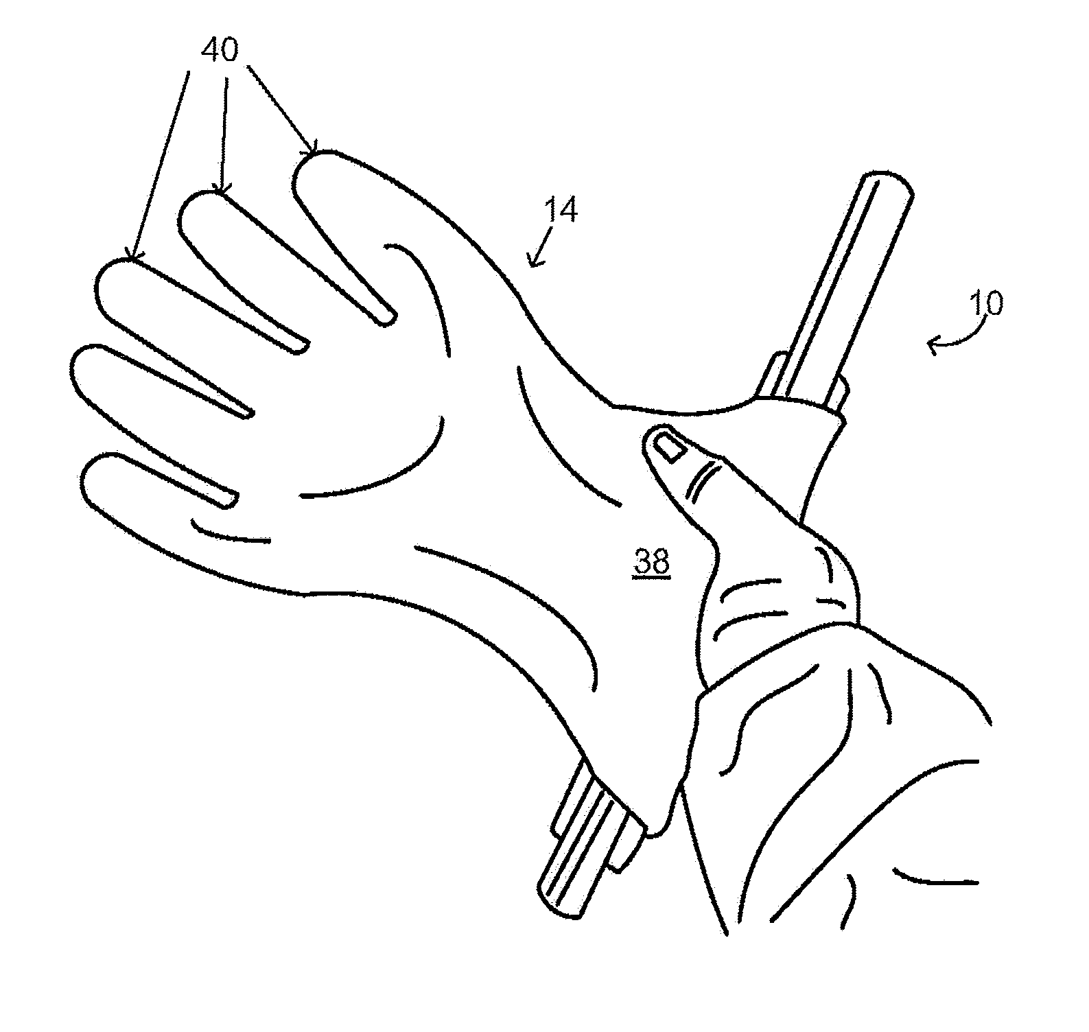
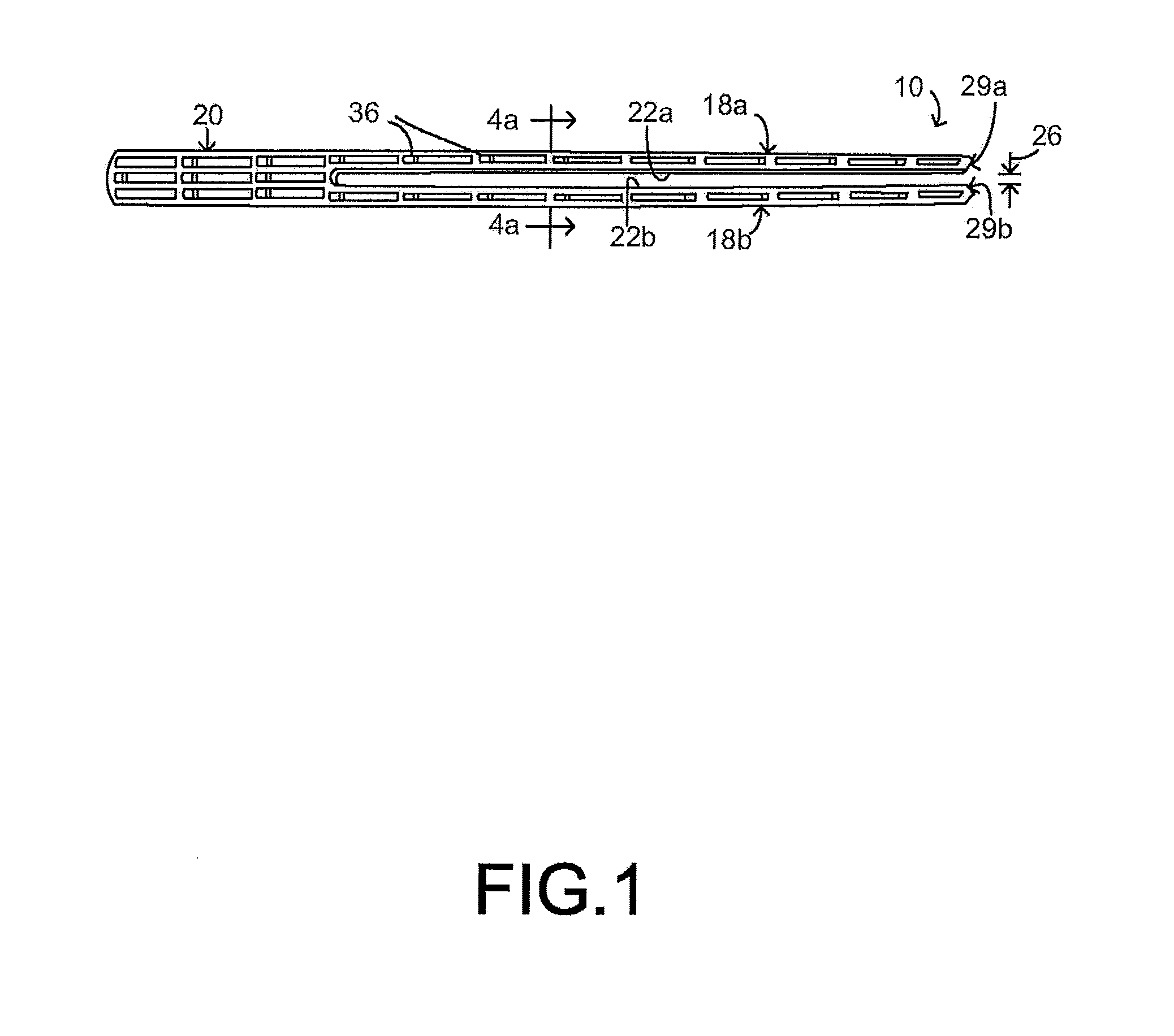
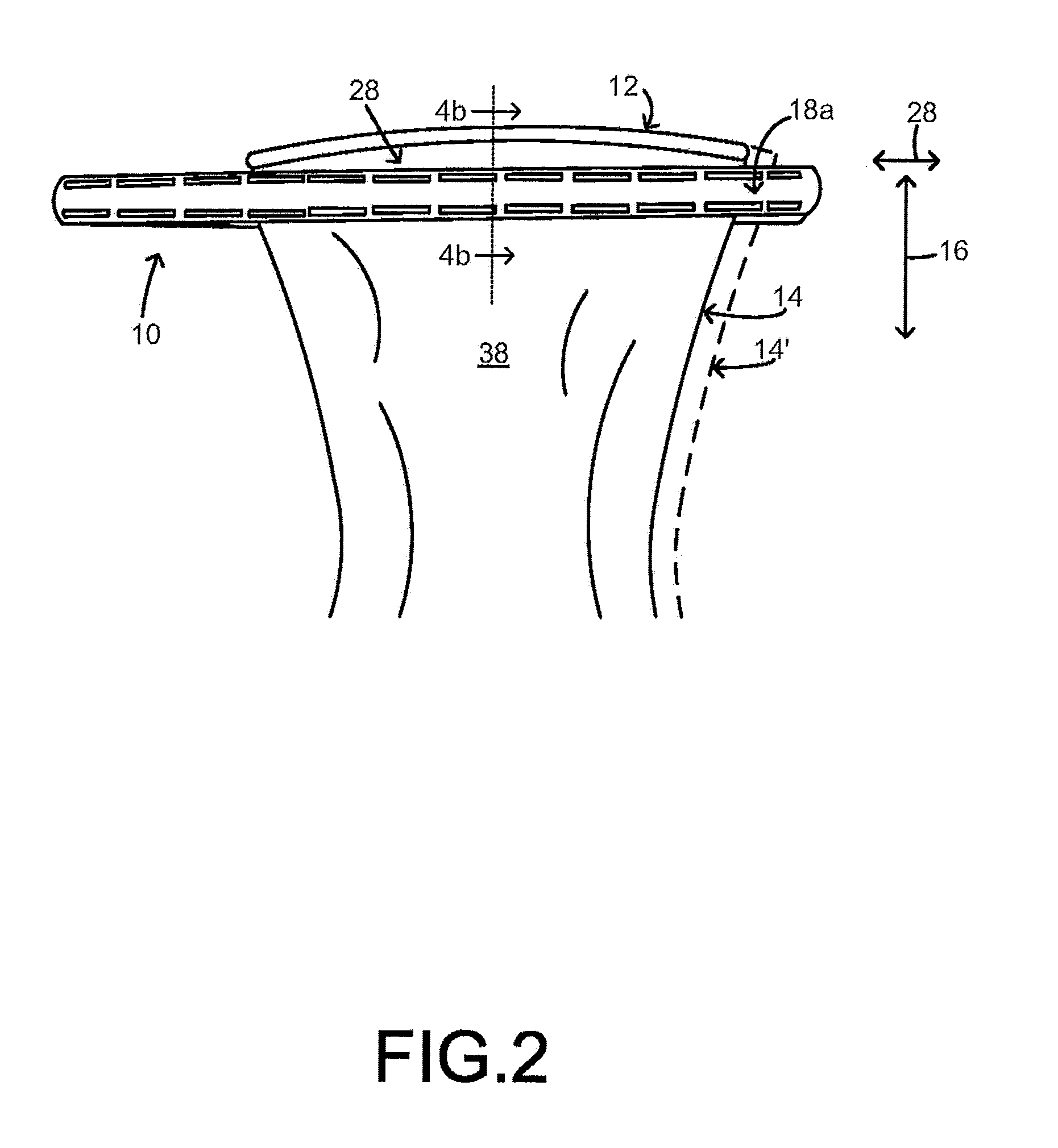
[0020]FIG. 1 shows an exemplary glove testing or spool device 10 constructed in accordance with the present invention. Referring to FIG. 2, the device is configured to receive the open mouth 12 of an insulative glove 14, particularly a natural or synthetic rubber glove of the type used by linemen or electricians to guard against electrical shock. As discussed further below, the device is configured to be moved relative to the lengthwise direction 16 of the glove so as to successively seal shut each portion of the glove passed by the device. Here and in the claims, the phrase “moved relative to” is merely intended to indicate relative movement so as to cover movement by the device alone, the glove alone, or both the device and glove together. As each portion of the glove passed by the device is sealed shut, the air trapped in the glove progressively inflates the glove. In particular, starting adjacent the open mouth, the glove is preferably rolled about the spool device 10 so as to infl


PUM


Abstract

The present invention relates to a glove testing device and method for air testing of gloves particularly of the insulative type used by linemen and electricians. The device may be moved relative to the lengthwise direction of the glove to successively seal shut securely each portion of the glove passed by the device so that air trapped in the glove progressively inflates the glove. In particular, the glove may be rolled about the testing or spool device starting adjacent the glove's open mouth either by rotating the device or wrapping the glove or by a combination of these movements. The device may include cantilevered arms forming a lateral gap for lateral insertion of the glove's end portion and may have rounded outer surfaces that avoid placing sharp folds in the glove during the rolling operation.

Description


Claims


Application Information

Patent Timeline
Owner SHIPLEY RANDALL L
Why Eureka
Try Eureka