Embedded opcode within an intermediate value passed between instructions

Active Publication Date: 2012-08-09
ARM LTD
View PDF5 Cites 0 Cited by
  • Summary
  • Abstract
  • Description
  • Claims
  • Application Information

AI Technical Summary

Benefits of technology

[0020]As an example, a generic evaluation of a power function ab may be performed with the generic sequence of program instructions in the general case and one level of precision via the first execution path. However, in the circumstance that the values of either a or b are such that the general power function matches another data processing function for which a different dedicated instruction is provided (e.g. a2), then using this different dedicated instruction as the substitute instruction to instead evaluate the data processing function via this alternative substitute instruction which may be calculated at a second different pr

Problems solved by technology

As an example, a complex data processing function may be computationally intensive to evaluate an

Method used


Image

  • Embedded opcode within an intermediate value passed between instructions
  • Embedded opcode within an intermediate value passed between instructions
  • Embedded opcode within an intermediate value passed between instructions

Examples


Embodiment Construction

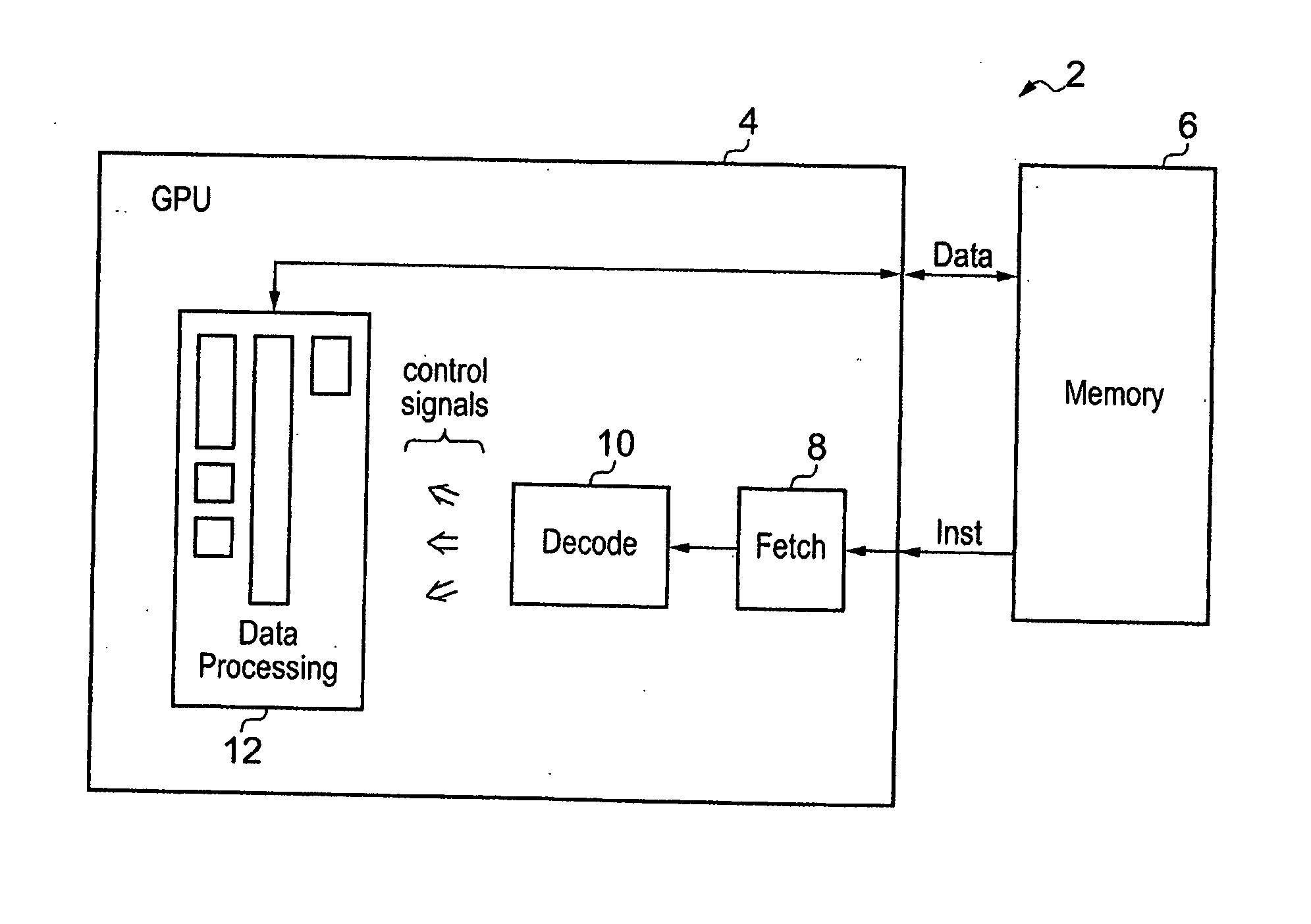
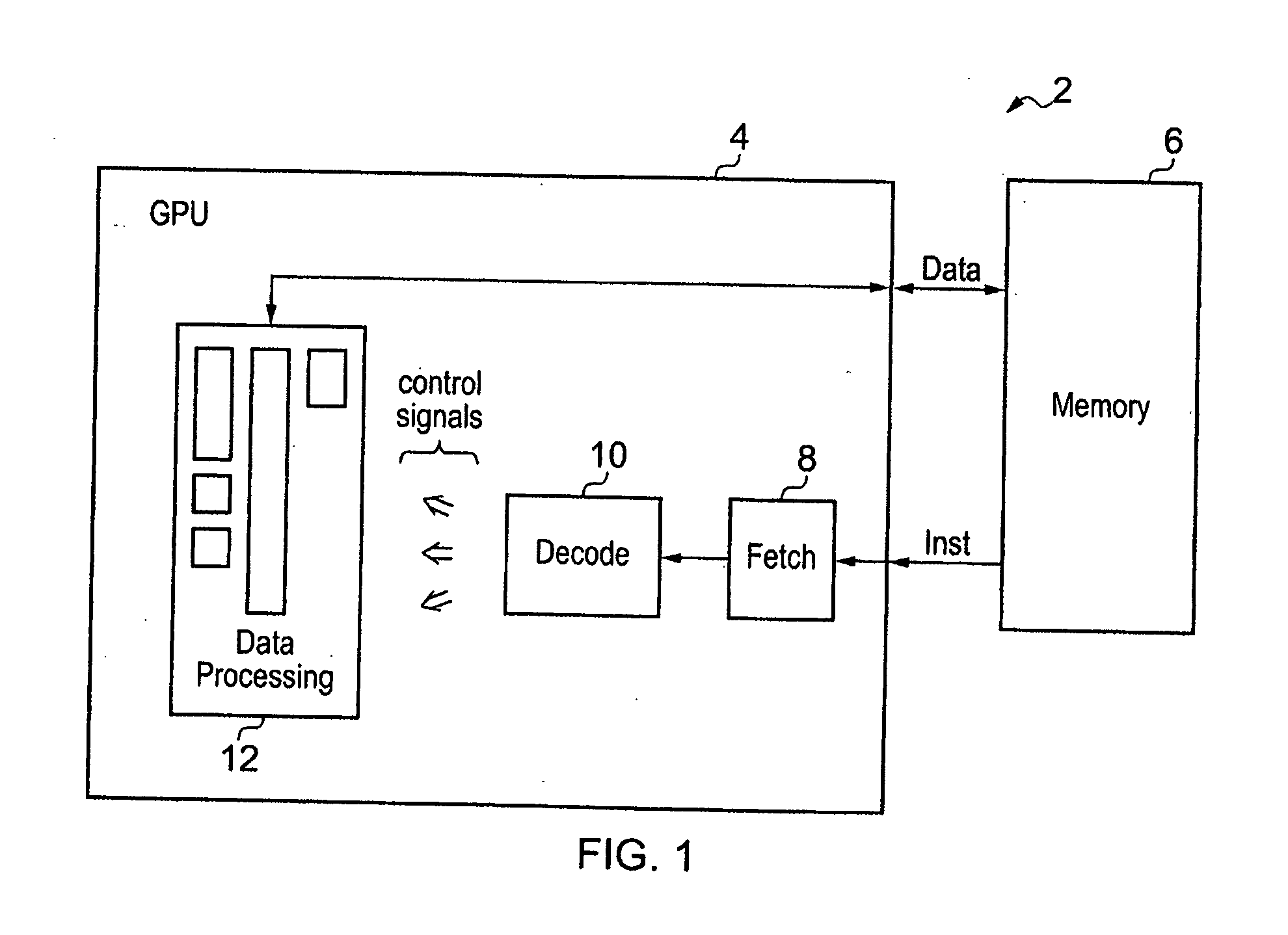
[0045]FIG. 1 schematically illustrates a data processing system 2 including a graphics processing unit 4 coupled to a memory 6. The memory 6 stores program instructions to be executed and data values, such as graphics data values, to be manipulated. The graphics processing unit 4 includes fetch circuitry 8 for fetching program instructions from the memory 6. Instruction decoder circuitry 10 decodes the fetched program instructions and generates control signals for controlling data processing circuitry 12 to perform desired data processing operations. The data processing circuitry 12 may include a plurality of execution pipelines, such as arithmetic pipeline, a SIMD pipeline, a floating point pipeline etc.

[0046]In the context of a graphics processing unit 4 when processing throughput may be more significant than latency, it is known to provide processing pipelines which are deep and are arranged such that they do not stall when executing a sequence of program instructions to evaluate a


PUM


Abstract

A data processing system 2 is used to evaluate a data processing function by executing a sequence of program instructions including an intermediate value generating instruction Inst0 and an intermediate value consuming instruction Inst1. In dependence upon one or more input operands to the evaluation, an embedded opcode within the intermediate value passed between the intermediate value generating instruction and the intermediate value consuming instruction may be set to have a value indicating that a substitute instruction should be used in place of the intermediate value consuming instruction. The instructions may be floating point instructions, such as a floating point power instruction evaluating the data processing function ab.

Description


Claims


Application Information

Patent Timeline
Owner ARM LTD
Why Eureka
Try Eureka