Microwave irradiation apparatus

Active Publication Date: 2012-08-23
TOKYO ELECTRON LTD
View PDF5 Cites 23 Cited by
  • Summary
  • Abstract
  • Description
  • Claims
  • Application Information

AI Technical Summary

Benefits of technology

[0017]With this configuration, while the microwave is effectively irradiated to the target object, the target object can be effectivel

Problems solved by technology

However, a conventional microwave irradiation apparatus cannot sufficiently control the temperature of the wafer.
However, in some processes, the power of the microwa

Method used


Image

  • Microwave irradiation apparatus
  • Microwave irradiation apparatus
  • Microwave irradiation apparatus

Examples


Embodiment Construction

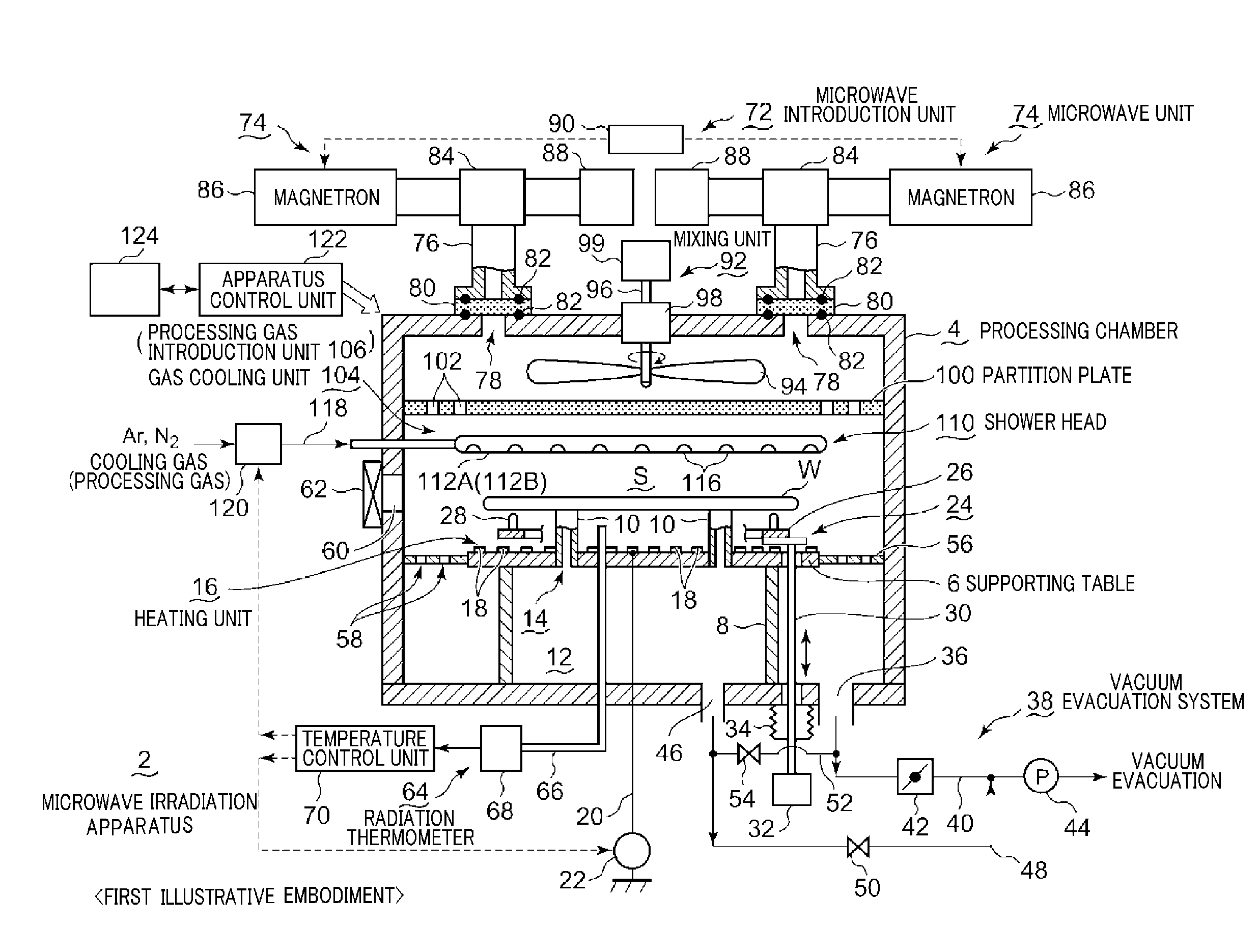
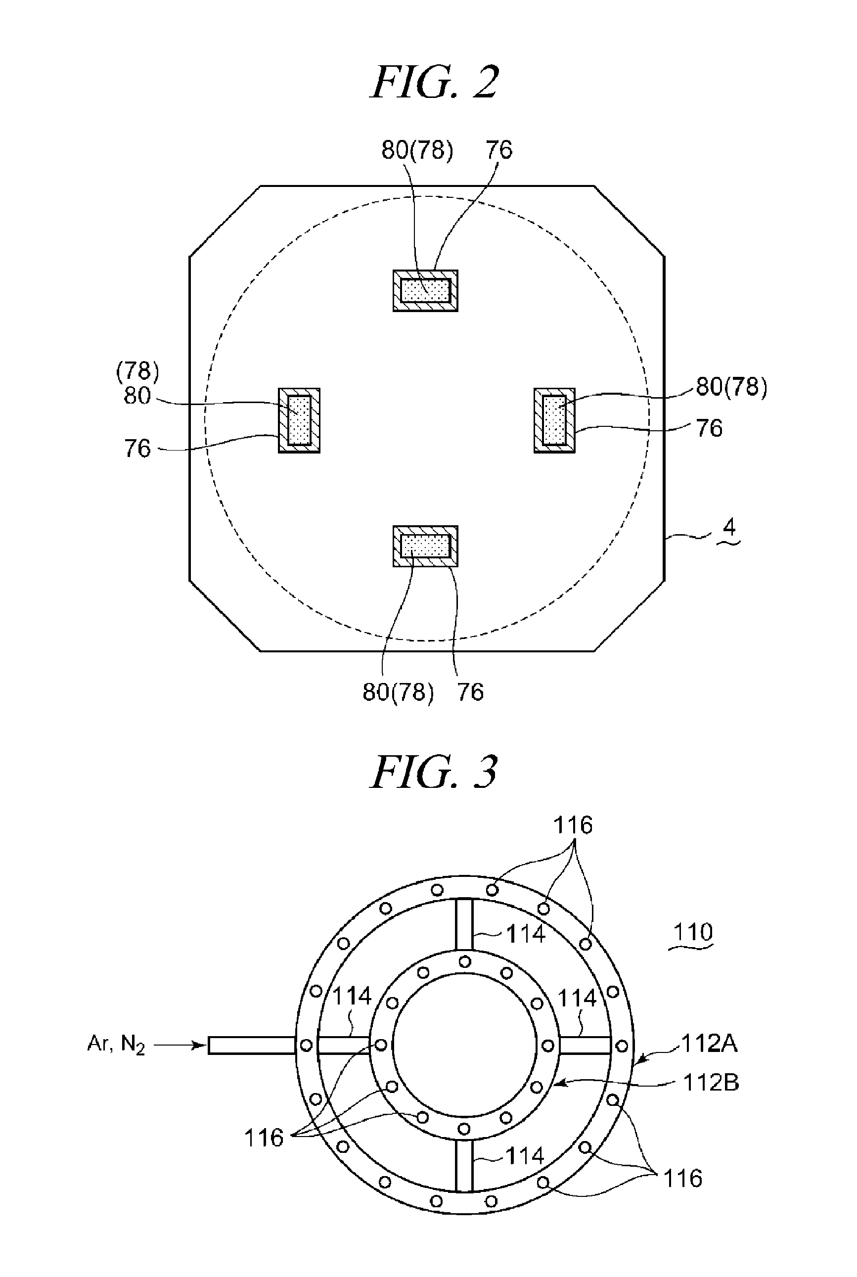
[0029]Hereinafter, a microwave irradiation apparatus in accordance with an illustrative embodiment will be described with reference to the accompanying drawings. FIG. 1 is a configuration view showing a microwave irradiation apparatus in accordance with a first illustrative embodiment. FIG. 2 shows waveguides of a microwave introduction unit positioned at a ceiling of a processing chamber. FIG. 3 shows a bottom surface of a shower head of a gas cooling unit (a processing gas introduction unit).

First Illustrative Embodiment

[0030]As depicted in the drawings, a microwave irradiation apparatus 2 includes a cylindrical processing chamber 4 made of aluminum, an aluminum alloy or stainless steel, and the inside of processing chamber 4 has a circular cross section shape. Within the processing chamber 4, a supporting table having a circular plate shape is supported by a cylindrical supporting column 8 standing uprightly from a bottom portion of the processing chamber 4. The supporting table 6 a


PUM


Abstract

There is provided a microwave irradiation apparatus capable of independently controlling a temperature of a target object while irradiating microwave to the target object. The microwave irradiation apparatus 2 includes a processing chamber 4 configured to be vacuum-evacuated; a supporting table 6 configured to support the target object; a processing gas introduction unit 106 configured to introduce a processing gas into the processing chamber; a microwave introduction unit 72 configured to introduce the microwave into the processing chamber; a heating unit 16 configured to heat the target object; a gas cooling unit 104 configured to cool the target object by a cooling gas; a radiation thermometer 64 configured to measure a temperature of the target object; and a temperature control unit 70 configured to adjust the temperature of the target object by controlling the heating unit and the gas cooling unit based on the temperature measured by the radiation thermometer.

Description


Claims


Application Information

Patent Timeline
Owner TOKYO ELECTRON LTD
Why Eureka
Try Eureka