Surgical tool holder

a tool holder and surgical technology, applied in the field of surgical tool holders, can solve the problems of non-patient-fixed tool holders, affecting the operation efficiency of surgical instruments, and requiring patient movement during surgery, and causing significant sensitivity to liquids or debris

Inactive Publication Date: 2012-11-29
MANOLIDIS SPIROS
View PDF17 Cites 55 Cited by
  • Summary
  • Abstract
  • Description
  • Claims
  • Application Information

AI Technical Summary

Benefits of technology

The invention relates to an improved mechanism used with two different parts on a button or switch that can lock together securely when they are pressed downward by users' fingers without being easily dislodged from their hands during use. This makes it easier for people who have trouble typing because there will always come across any difficulty where pressing one part causes them accidentally activating other buttons while still having control over how much pressure was applied through these keys.

Problems solved by technology

This patent describes various technical solutions related to improving the stability and accuracy of medical procedures involving implanted objects like catheters and wires. These techniques involve attaching them securely onto the object without causing damage themselves while also allowing easy removal after use. Additionally, they should allow for quick assembly/disassembly even under difficult conditions where it could harm healthy individuals nearby.

Method used


Image

  • Surgical tool holder
  • Surgical tool holder
  • Surgical tool holder

Examples


Embodiment Construction

[0040]Devices and apparatuses for holding surgical tools during surgery are described herein, with reference to examples and exemplary embodiments. Specific terminology is employed in describing examples and exemplary embodiments. However, the disclosure of this patent specification is not intended to be limited to the specific terminology so selected and it is to be understood that each specific element includes all technical equivalents that operate in a similar manner.

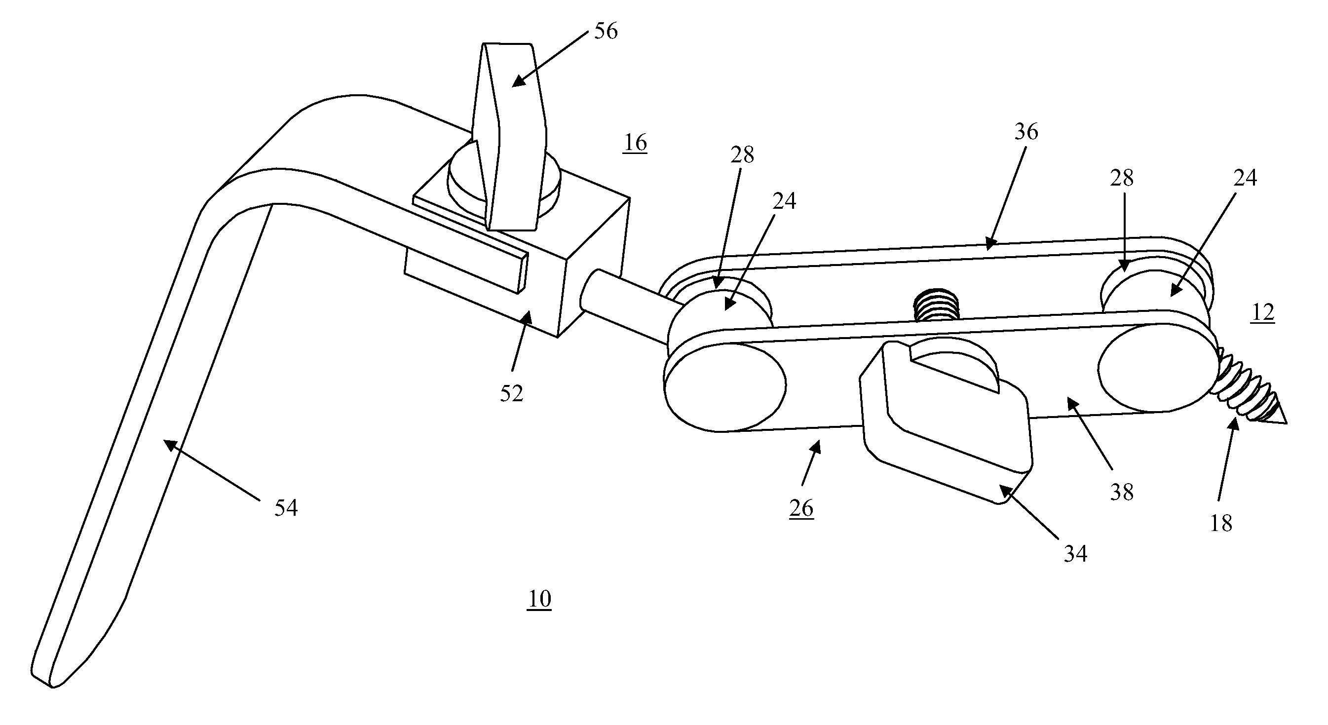
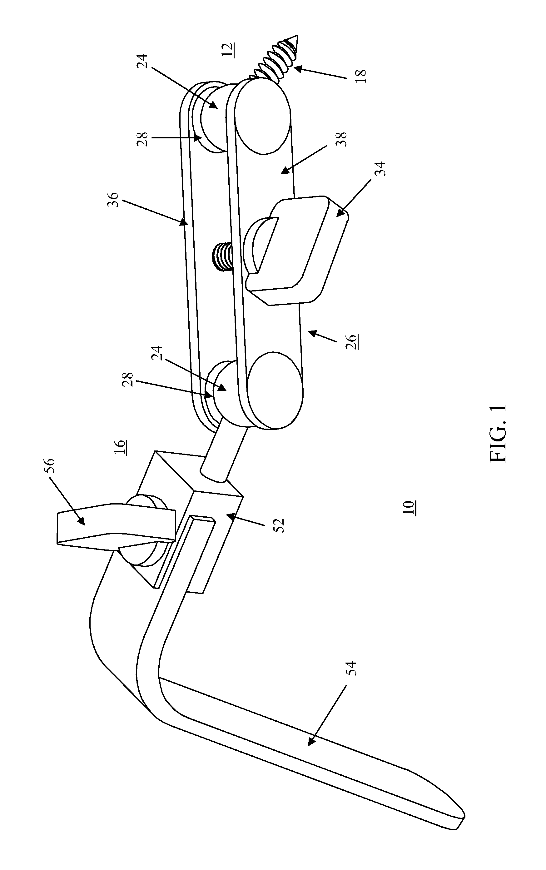
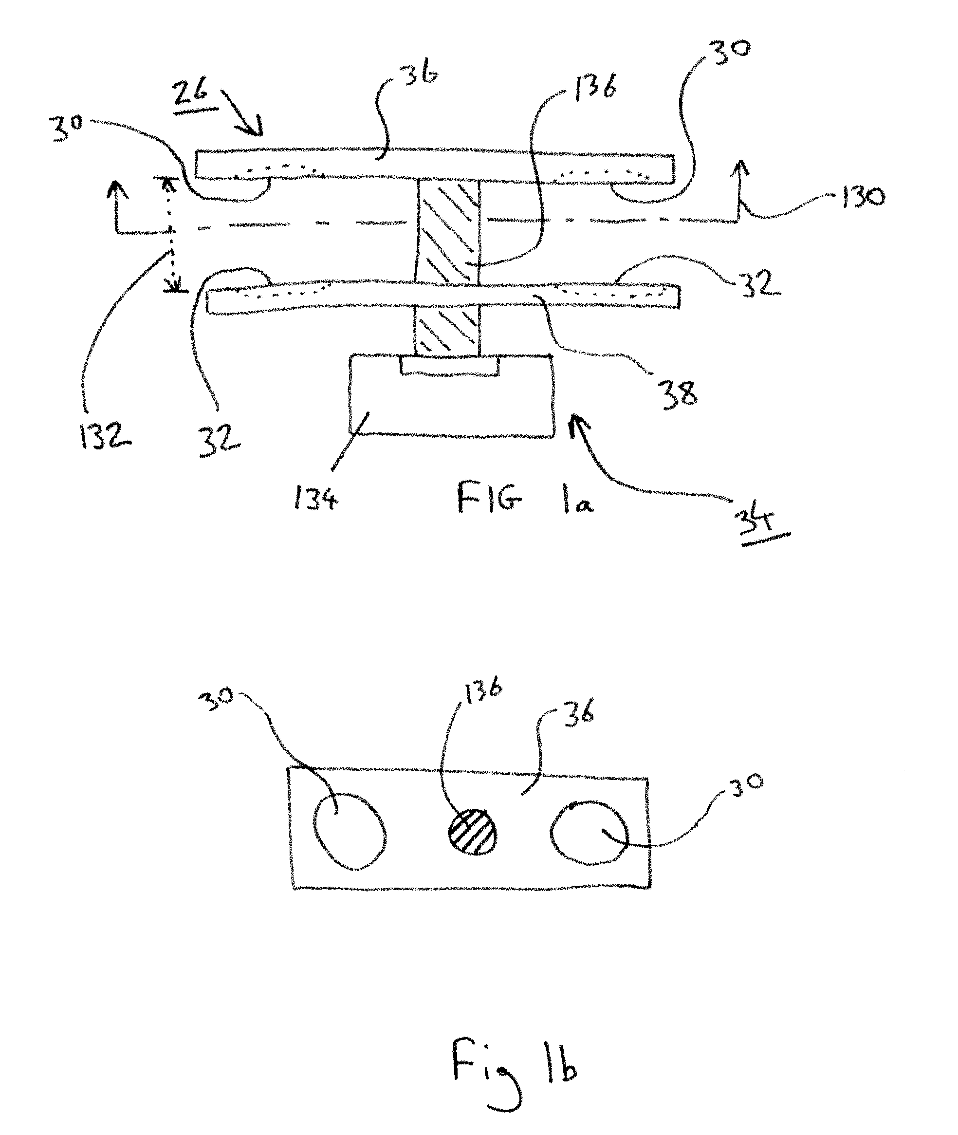
[0041]A surgical tool holder 10 is generally comprised of a base member 12, one or more intermediary members, and a tool engaging member 16. One example of a surgical tool holder 10 is shown in FIG. 1. According to the present invention, the base member 12 is attached to the patient's body so as to remain fixed during surgery. For example, the base member 12 may be screwed into the skull 11 of a patient undergoing neurosurgery, as shown in FIG. 2, and a brain retractor 54 at the distal end of surgical tool holder 10 ma


PUM


Abstract

Apparatuses are provided to hold surgical tools during surgery. Such apparatuses may be fixed to a patient's body and include a base member, tool engagement member and one or more intermediary members. Each member may be attached to another by a knob and mating engagement section. Fixation between members may be provided individually for each attachment or may be provided so as to fix more than one attachment at a time.

Description


Claims


Application Information

Patent Timeline
Owner MANOLIDIS SPIROS
Why Eureka
Try Eureka