Stereoscopic display apparatus

a stereoscopic display and display device technology, applied in the field of display devices, can solve the problems of high cost of manufacturing abnormal operation of the shutter glasses, and inability to receive infrared signals, so as to improve the integrity, reduce the cost of the stereoscopic display apparatus of the present invention, and improve the appearance of the stereoscopic display apparatus

Inactive Publication Date: 2012-12-20
INNOLUX CORP +1
View PDF3 Cites 2 Cited by
  • Summary
  • Abstract
  • Description
  • Claims
  • Application Information

AI Technical Summary

Benefits of technology

This patented technology allows for stereoscopic displays without requiring an extra component like an infrared emitter. Instead, it uses a special type of material that lets out visible lights when exposed to certain wavelengths of electromagnetic radiation. These lights are then captured by a shutter system where they control how long the lights go through. By doing this, the display becomes more visually appealing and less expensive than traditional methods.

Problems solved by technology

The technical problem addressed in this patent is how to create a stereoscopic display apparatus that has both good visual acuity and minimal costs, while still maintaining its appearance and functionality.

Method used


Image

  • Stereoscopic display apparatus
  • Stereoscopic display apparatus
  • Stereoscopic display apparatus

Examples


Embodiment Construction

[0032]The present invention will be apparent from the following detailed description, which proceeds with reference to the accompanying drawings, wherein the same references relate to the same elements.

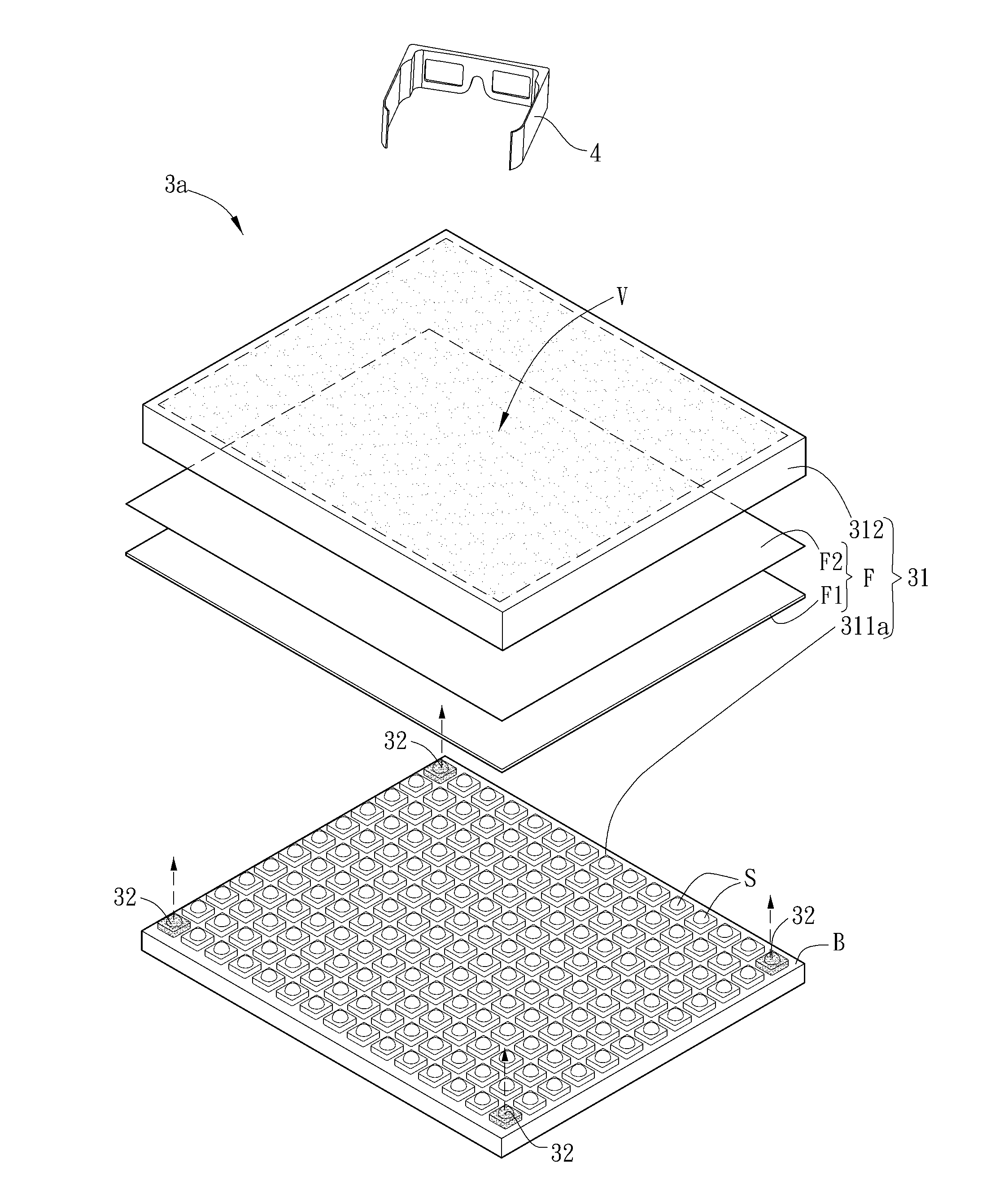
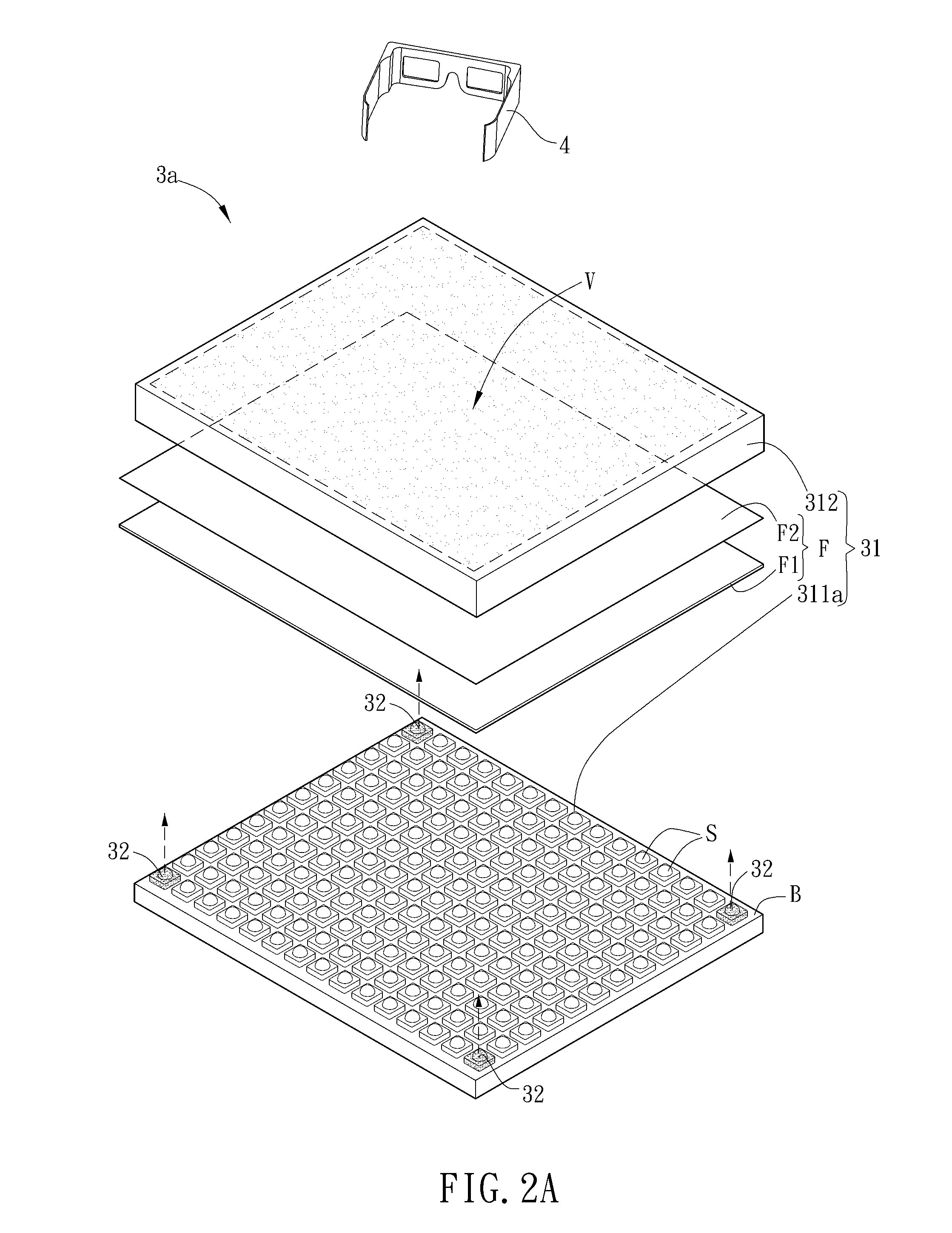
[0033]FIG. 2A is an illustration of an aspect of a stereoscopic display apparatus 3a according to a preferred embodiment of the present invention. Referring to FIG. 2A, the stereoscopic display apparatus 3a is cooperated with a shutter apparatus 4, and a shutter unit of the shutter apparatus 4 is substantially disposed between human eyes and the stereoscopic display apparatus 3a. In other words, the shutter unit is disposed in an optical path between human eyes and the stereoscopic display apparatus 3a, so that the user can view the stereoscopic display apparatus 3a through the shutter apparatus 4. The stereoscopic display apparatus 3a includes a display module 31 and an infrared emitting device 32. In this embodiment, the stereoscopic display apparatus 3a can be used as a display device


PUM


Abstract

A stereoscopic display apparatus is cooperated with a shutter apparatus. The stereoscopic display apparatus includes a display module and an infrared emitting device. The display module has a viewable area and an optical sheet. The infrared emitting device is disposed in the display module. The light emitted from the infrared emitting device passes through the optical sheet and the viewable area and be received by the shutter apparatus to control it. The stereoscopic display apparatus can reduce the cost and make the appearance of the stereoscopic display apparatus have better integrity.

Description


Claims


Application Information

Patent Timeline
Owner INNOLUX CORP
Why Eureka
Try Eureka