Self-loosening capsule

a self-loosening, capsule technology, applied in the direction of steering column, steering parts, vehicle components, etc., can solve the problem of unsuitably high load required for breaking away

Inactive Publication Date: 2013-12-05
STEERING SOLUTIONS IP HLDG
View PDF1 Cites 9 Cited by
  • Summary
  • Abstract
  • Description
  • Claims
  • Application Information

AI Technical Summary

Benefits of technology

This patented technology describes how a steer's wheel can have its own way out when it gets stuck or needs maintenance without being removed by hand alone. It uses a special device that locks onto one part on each side of the car's frame. When this happens, the wheels are pulled away towards their original positions.

Problems solved by technology

This patented describes how current methods used on vehicles with energy absorption systems involve attaching a separate part called a cap or shell around each end of the system's support structure (mount) before injection molded plastomer material fills any gaps create weak points where cracks could occur during crashes.

Method used


Image

  • Self-loosening capsule
  • Self-loosening capsule
  • Self-loosening capsule

Examples


Embodiment Construction

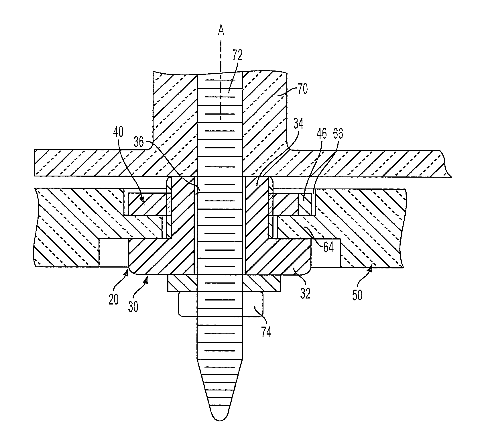
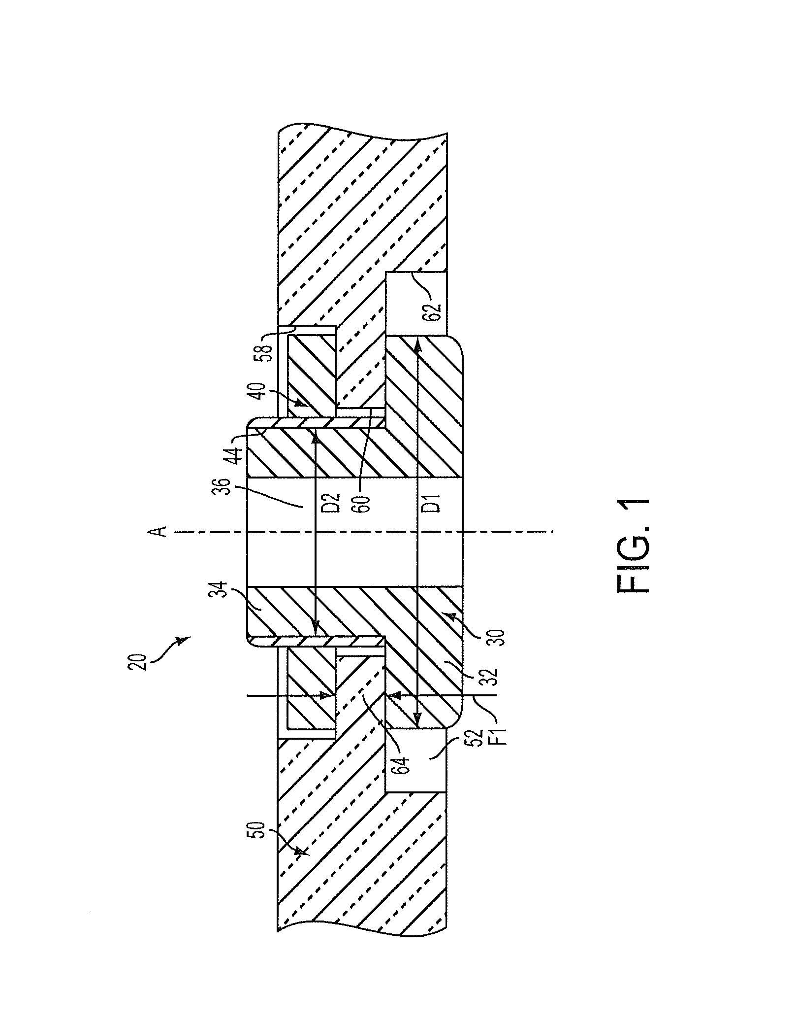
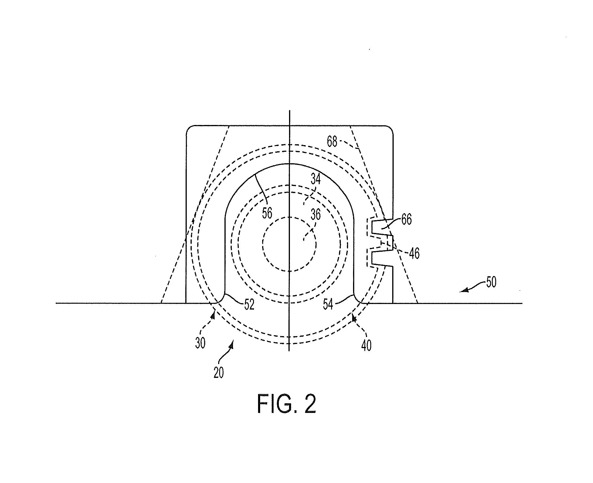
[0015]Referring now to the Figures, where the invention will be described with reference to specific embodiments, without limiting same, FIG. 1 is a cross section of a self-loosening capsule assembly 20 comprising a capsule 30 and capsule nut 40. The self-loosening capsule assembly 20 is installed in a mounting bracket 50 of a steering column (not shown). The mounting bracket 50 is configured to mount the steering column in a vehicle.

[0016]In an exemplary embodiment, the capsule 30 is round in shape and includes a head 32 and body 34. The head 32 has a first outer diameter D1 and the body has a second outer diameter D2. The first outer diameter is greater than the second outer diameter. The head 32 is generally disk shaped.

[0017]The body 34 extends from the head 32. In an exemplary embodiment, the body 34 extends along a first axis ‘A’. An outer surface of the body 34 includes an external thread. A central bore 36 extends through the head 32 and body 34 along the axis ‘A’. The central


PUM


Abstract

A steering column having a mounting bracket and a self-loosening capsule assembly configured for attachment to an adjacent vehicle component is provided. The mounting bracket includes an installation slot, a flange extending within the installation slot and a bracket keying mechanism positioned at a periphery of the installation slot. The self-loosening capsule assembly is received in the installation slot, and includes a capsule and capsule nut. The capsule includes a head and a body extending from the head, the body having a threaded outer surface, the head having a larger outer diameter than the body. The capsule nut includes a threaded inner surface for threaded coupling to the capsule and is movable so as to apply a first clamping force to the flange of the mounting bracket between the head and the capsule nut and a keying mechanism configured to interface with the bracket keying mechanism.

Description


Claims


Application Information

Patent Timeline
Owner STEERING SOLUTIONS IP HLDG
Why Eureka
Try Eureka