Conductor Arrangement with a Dielectric Standing Wave Trap

a dielectric standing wave and dielectric technology, applied in waveguides, waveguide type devices, instruments, etc., can solve the problems of metal structure being problematic in magnetic resonance systems, and achieve the effect of high-quality dielectric resonator devices and simple manner

Inactive Publication Date: 2014-08-07
SIEMENS HEALTHCARE GMBH
View PDF4 Cites 1 Cited by
  • Summary
  • Abstract
  • Description
  • Claims
  • Application Information

AI Technical Summary

Benefits of technology

The present technology allows for precise adjustment of an electrical component called a capacitor or inductor used within electronic devices such as radios. By rotating around its own centerline with threads attached at different locations throughout it, each part can have very high accuracy during manufacturing process. This results in improved performance over time compared to previous methods due to better alignment between components.

Problems solved by technology

The technical problem addressed by this patented inventions relates to improving the design of electronic devices with inductors or antennas due to their ability to generate stable signals even when subjected to strong external fields like those caused during medical procedures such as MRI scans.

Method used


Image

  • Conductor Arrangement with a Dielectric Standing Wave Trap
  • Conductor Arrangement with a Dielectric Standing Wave Trap
  • Conductor Arrangement with a Dielectric Standing Wave Trap

Examples


Embodiment Construction

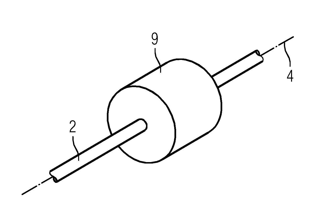
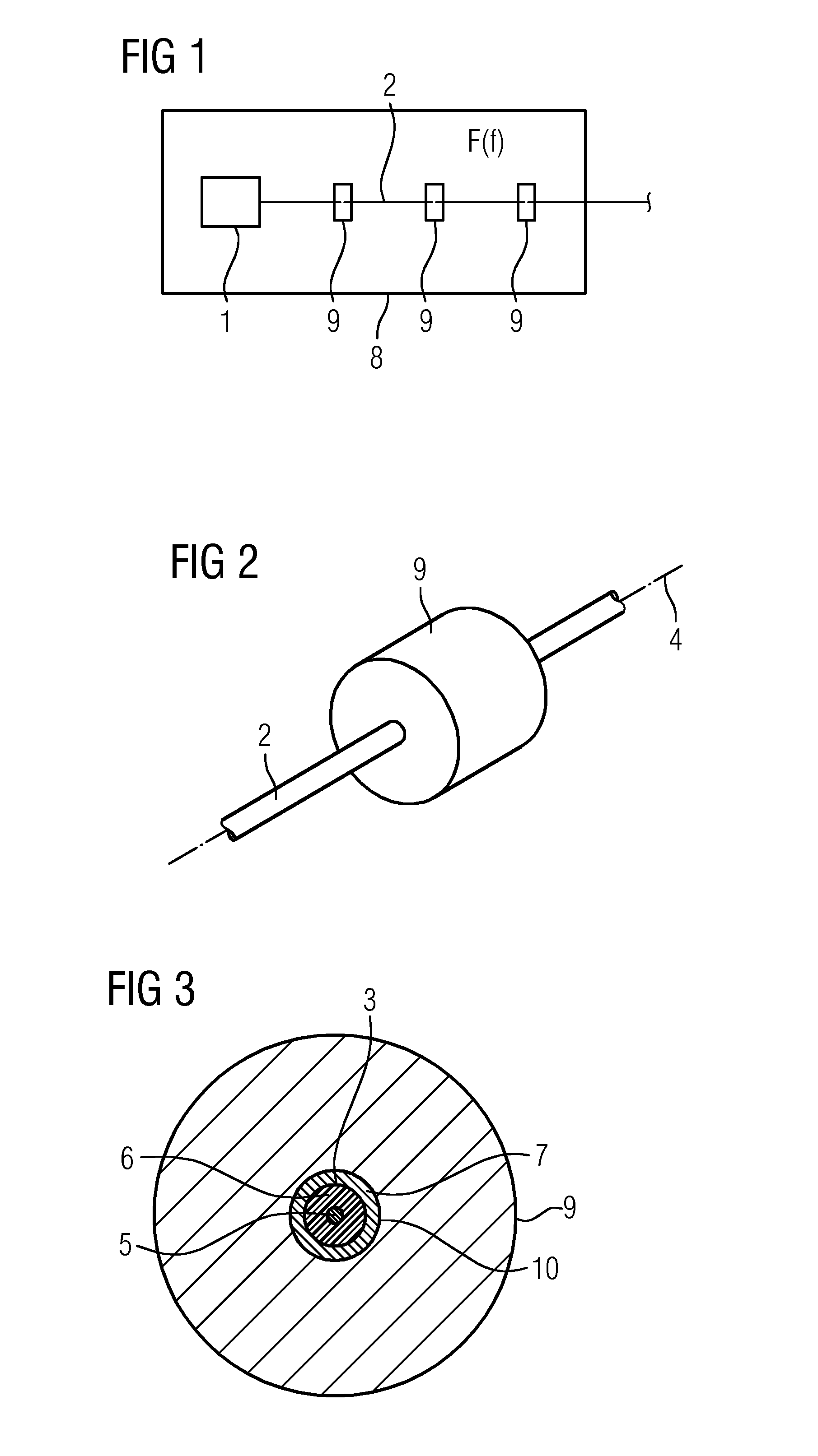
[0021]According to FIG. 1, an element 1 of a magnetic resonance system (e.g., a local coil) is connected to another device (not illustrated in FIG. 1) via a cable 2. According to FIGS. 2 to 5, the cable 2 has a conductor 3 that extends along a conductor axis 4. According to FIG. 1, the cable 2 is in the form of a coaxial cable. The coaxial cable 2 has an internal conductor 5. The conductor 3 is in the form of a shield of the coaxial cable 2. An insulation 6 is arranged between the internal conductor 5 and the conductor 3. A cable sheath 7 is arranged around the outside of the shield 3. This refinement, in which the cable 2 is in the form of a coaxial cable, constitutes the general case. However, in individual cases, the conductor 3 may be a “normal” conductor that is surrounded only by a cable sheath 7 or only by a core insulation.

[0022]The conductor 3 is exposed to an RF field F from the outside (e.g., to the excitation field of a whole-body transmission antenna 8 of the magnetic reso


PUM


Abstract

A conductor arrangement includes a conductor that extends along a conductor axis. The conductor arrangement also includes a standing wave trap to which the conductor is coupled in order to damp standing waves that are excited by an RF field from outside the conductor arrangement. The standing wave trap is in the form of a dielectric resonator device.

Description


Claims


Application Information

Patent Timeline
Owner SIEMENS HEALTHCARE GMBH
Why Eureka
Try Eureka