Locking Gun Rack System With Quick Deployment

Inactive Publication Date: 2014-09-18
SECURE WEAPON SYST LLC
View PDF19 Cites 15 Cited by
  • Summary
  • Abstract
  • Description
  • Claims
  • Application Information

AI Technical Summary

Benefits of technology

[0005]The current invention combines the safety currently offered in many rack systems, but provides much higher standard of security in addition to immediate deployment. As noted there are currently no long gun racks on the market with RFID/keypad/biometric technology. There are handgun “strongboxes” that are biometric, or have some form of electronic or non-electric keypad, but nothing for rifles.

Problems solved by technology

Most rifle/shotgun racks for home and law enforcement use are extremely secure, but do not allow the end user to deploy the weapon system rapidly in an evolving emergency situation.
While the current market has racks that allow the user to immediately deploy the rifle/shotgun, security becomes very limited.
This technology has never been adapted to a long gun rack.
The weakness of the system is that a criminal or other unauthorized person can break into a running police car and start pushing switches and buttons.
In addition, most undercover police cars in the US do not have a trunk mounted rack of any type.
They are slow and do not allow for immediate access to the weapon.
Some manufacturers have wall mount racks, but none of them have power, or a secure keypad/RFID design to allow for additional security.

Method used


Image

  • Locking Gun Rack System With Quick Deployment
  • Locking Gun Rack System With Quick Deployment
  • Locking Gun Rack System With Quick Deployment

Examples


Example

[0019]While the invention is susceptible to embodiments in many different forms, there are shown in the drawings and will be described herein, in detail, the preferred embodiments of the present invention. It should be understood, however, that the present disclosure is to be considered an exemplification of the principles of the invention and is not intended to limit the spirit or scope of the invention and / or the embodiments illustrated.

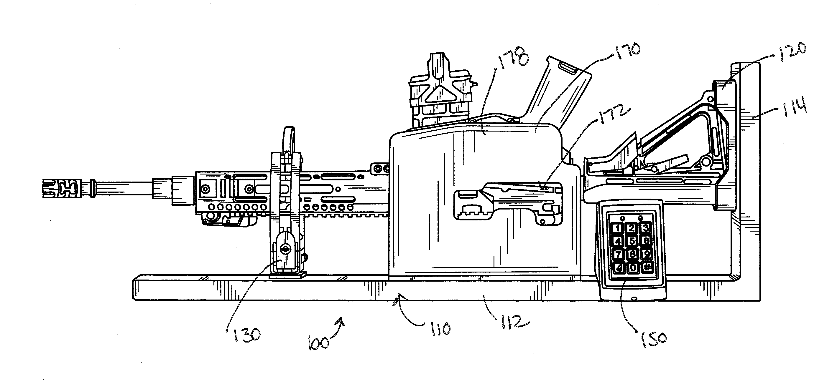
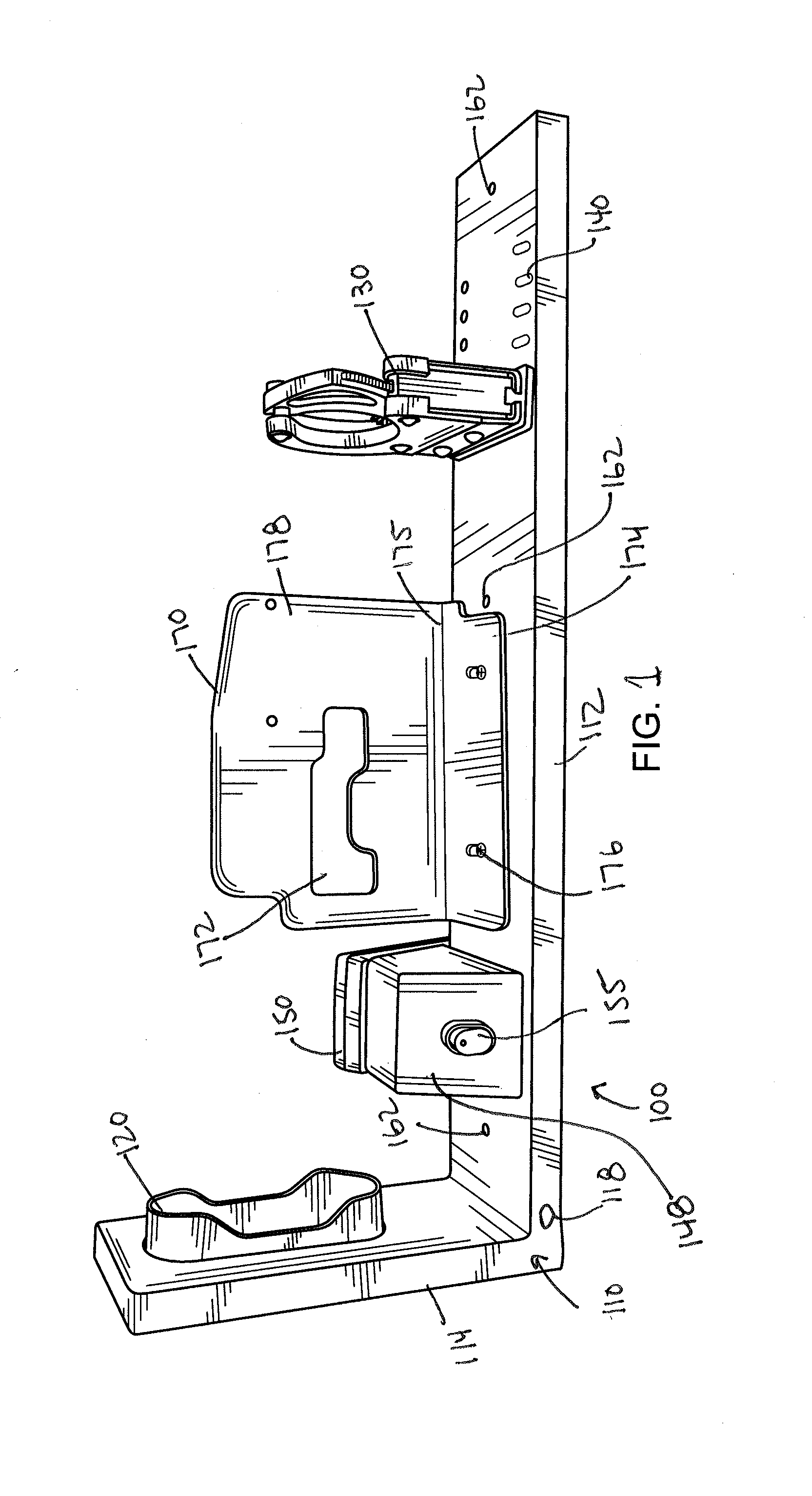
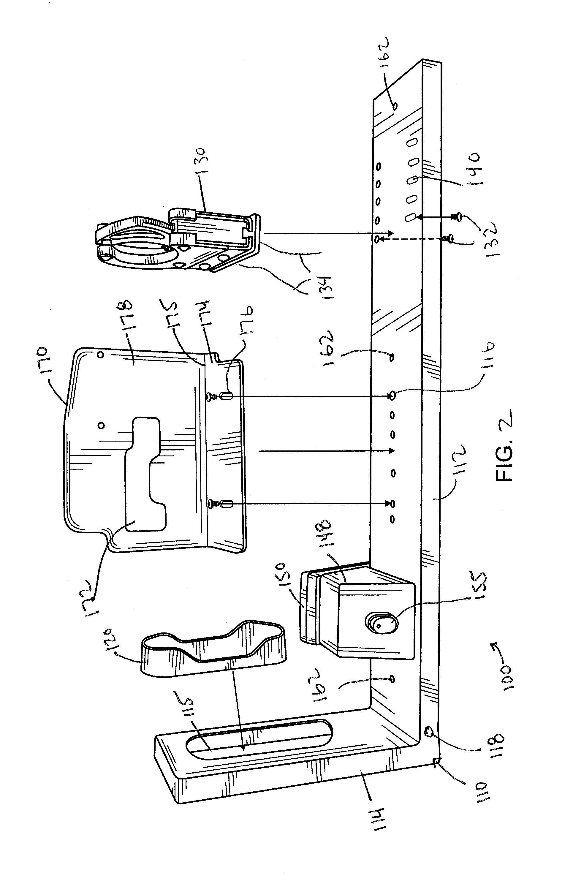
[0020]Referring now to FIGS. 1 through 9, there is shown a gun rack assembly 100 in accordance with various embodiments of the present invention, employed with a rifle or long gun 10. The gun rack assembly 100 is powered by any twelve (12) volt power supply (not shown). Any vehicle electric system, or the supplied power supply / adapter will power the system. It can also be battery powered, or have a battery back-up system spliced in line in case of power failure.

[0021]The gun rack assembly 100 includes a L shaped style rack frame 110, formed by hav


PUM


Abstract

In one embodiment there is provided a long gun rack system. The system includes an L-shaped frame; a butt cap secured to the side to accommodate a butt end of the gun; a handcuff ratchet lock mechanism secured to the frame at a position to accommodate the barrel, the lock mechanism configured to unlock in response to the receipt of an electronic code or in response to a key; an electronic security mechanism secured to the frame and is in communication with the lock mechanism; and a side plate having a cut-out region is secured along the frame at a position defined between the lock mechanism and the frame, such that the cut-out region permits the plate to mount in close proximity to the long gun and blocks the removal of the takedown pins and/or the full movement of a charging handle.

Description


Claims


Application Information

Patent Timeline
Owner SECURE WEAPON SYST LLC
Why Eureka
Try Eureka