Golf bag divider accessory and method of making same
a bag divider and accessory technology, applied in the field of golf bags, can solve the problems of golf clubs aging, golf clubs being replaced, increasing the cost of playing golf, etc., and achieve the effect of convenient identification and access
- Summary
- Abstract
- Description
- Claims
- Application Information
AI Technical Summary
Benefits of technology
Problems solved by technology
Method used
Image

Examples
first embodiment
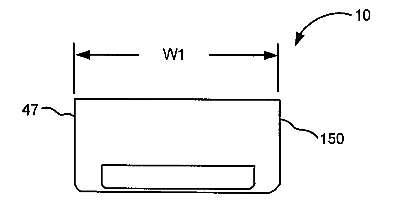
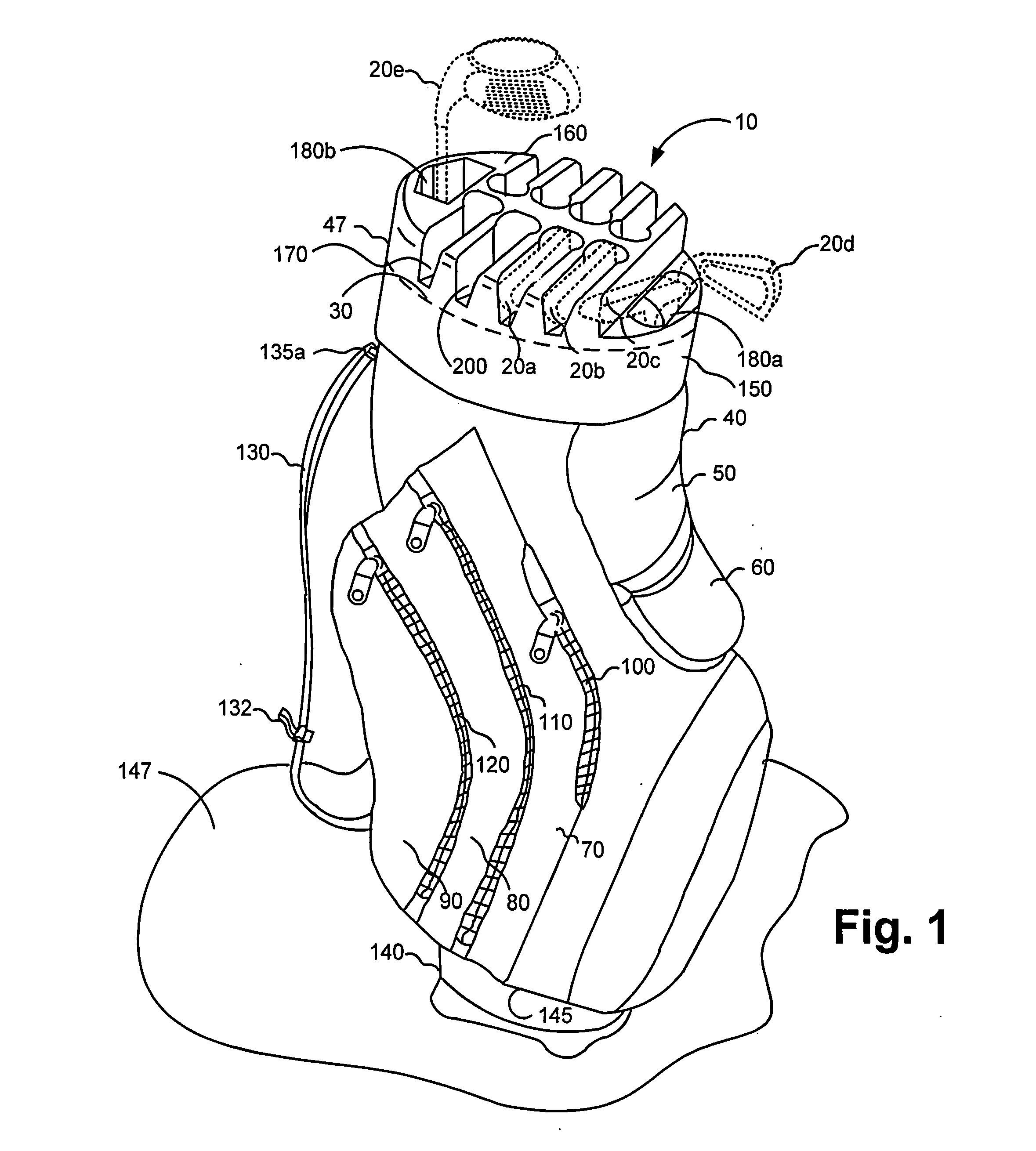
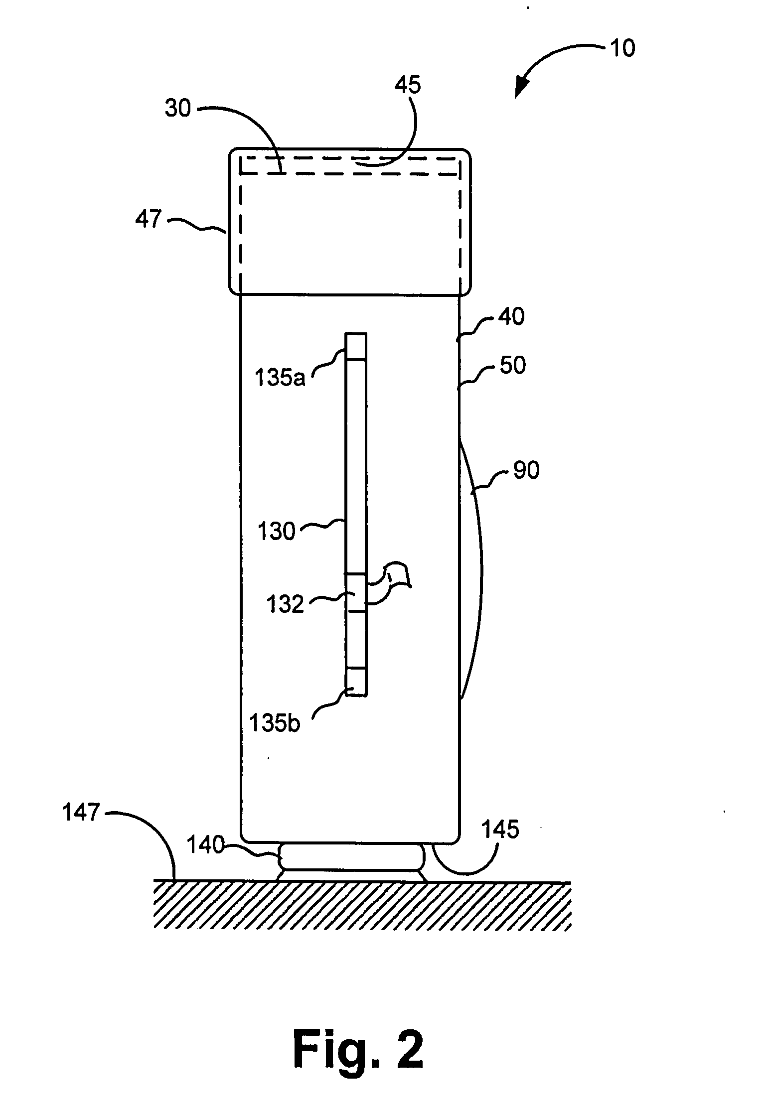
[0053]Therefore, with reference to FIGS. 1 and 2, there is shown a first embodiment golf bag divider accessory, generally referred to as 10, for maintaining a plurality of golf clubs 20a, 20b, 20c, 20d and 20e in a spaced-apart relationship. By way of example only, golf clubs 20a and 20b are irons, golf club 20c is a putter, golf club 20d is a “wedge” and golf club 20e is a “wood” or driver. Each of golf clubs 20a / 20b / 20c / 20d / 20e includes an elongate golf club shaft 23 and a golf club head 25 attached to golf club shaft 23. Although only four golf clubs are shown, it should be appreciated that golf bag divider accessory 10 (hereinafter “divider accessory 10”) is configured to hold a full complement of golf clubs (i.e., 14 golf clubs) for use by adults and teenagers. Alternatively, divider accessory 10 may be configured to hold a fewer number of golf clubs, such as in the case of a toy or junior golf club set and golf club bag properly sized for children. Golf clubs 20a / 20b /
fourth embodiment
[0064]With reference to FIGS. 16 and 17, a fourth embodiment golf bag divider accessory, generally referred to as 320, is there shown for maintaining a plurality of golf clubs 20a, 20b, 20c, 20d and 20e in a spaced-apart relationship. In this embodiment of golf bag divider accessory 320 (hereinafter “divider accessory 320”), a shell portion 330 is integrally formed atop a rigid, tubular golf bag 340 as a single unit, rather than being a separate component mountable on the golf bag. This embodiment of the invention may be manufactured using an injection mold manufacturing process, if the unit is formed from a polymer. Alternatively, the unit may be manufactured from a metal blank formed into the shape of a combination golf bag and divider accessory by means of a suitable stamping and welding process.
[0065]As best seen in FIG. 17, shell portion 330 of this fourth embodiment divider accessory 330 defines the previously mentioned apertures 180a / 180b, holes 190 and channels 200. In this r
fifth embodiment
[0066]In FIG. 18, a fifth embodiment golf bag divider accessory, generally referred to as 350, is there shown for maintaining the plurality of previously mentioned golf clubs 20a / 20b / 20c / 20d / 20e in a spaced-apart relationship (only some of which are shown). In this embodiment of golf bag divider accessory 350 (hereinafter “divider accessory 350”), a dome-shaped shell 360 is mounted atop rim portion 30 of golf bag 40 and defines a plurality of spaced-apart slanted openings 362 therethrough. In this regard, dome-shaped shell 360 has a convex outer surface 363 and defines a plurality of slanted holes 365 through surface 363, slanted channels 367 formed in surface 363, and slanted apertures 369 through surface 363 for receiving respective ones of the plurality of golf clubs 20a / 20b / 20c / 20d / 20e. Openings 365 and apertures 368 allow golf clubs 20a / 20b / 20c / 20d / 20e to be inclined at a predetermined angle phi “O” with respect to a vertical axis 369. The value of angle ph
PUM
 Abstract
Description
Claims
Application Information
 - R&D Engineer
- R&D Manager
- IP Professional
- Industry Leading Data Capabilities
- Powerful AI technology
- Patent DNA Extraction
Browse by: Latest US Patents, China's latest patents, Technical Efficacy Thesaurus, Application Domain, Technology Topic.
© 2024 PatSnap. All rights reserved.Legal|Privacy policy|Modern Slavery Act Transparency Statement|Sitemap