Bandgap reference voltage circuit and electronic apparatus thereof

a reference voltage circuit and reference voltage technology, applied in the direction of electric variable regulation, process and machine control, instruments, etc., can solve the problems of reference voltage instability, harm to the electric device, complicated internal circuit structure of the electric device, etc., and achieve the effect of reducing stability

Inactive Publication Date: 2015-02-19
ILI TECHNOLOGY CORPORATION
View PDF2 Cites 5 Cited by
  • Summary
  • Abstract
  • Description
  • Claims
  • Application Information

AI Technical Summary

Benefits of technology

The inventor's new design allows for better control over temperature and power supply during operation. It eliminates the need for extra components like resistors or transistors that could damage the system. This results in improved performance and reliability.

Problems solved by technology

This patent describes a problem with conventional electronic devices that require accurate reference voltages for proper functioning. These references are influenced by external factors such as temperature variations and can affect their performance. To solve this issue, the technical problem addressed in the patent is how to ensure stable reference voltages without causing errors or damaging the electric device being driven.

Method used


Image

  • Bandgap reference voltage circuit and electronic apparatus thereof
  • Bandgap reference voltage circuit and electronic apparatus thereof
  • Bandgap reference voltage circuit and electronic apparatus thereof

Examples


Embodiment Construction

[0019]The aforementioned illustrations and following detailed descriptions are exemplary for the purpose of further explaining the scope of the present invention. Other objectives and advantages related to the present invention will be illustrated in the subsequent descriptions and appended drawings.

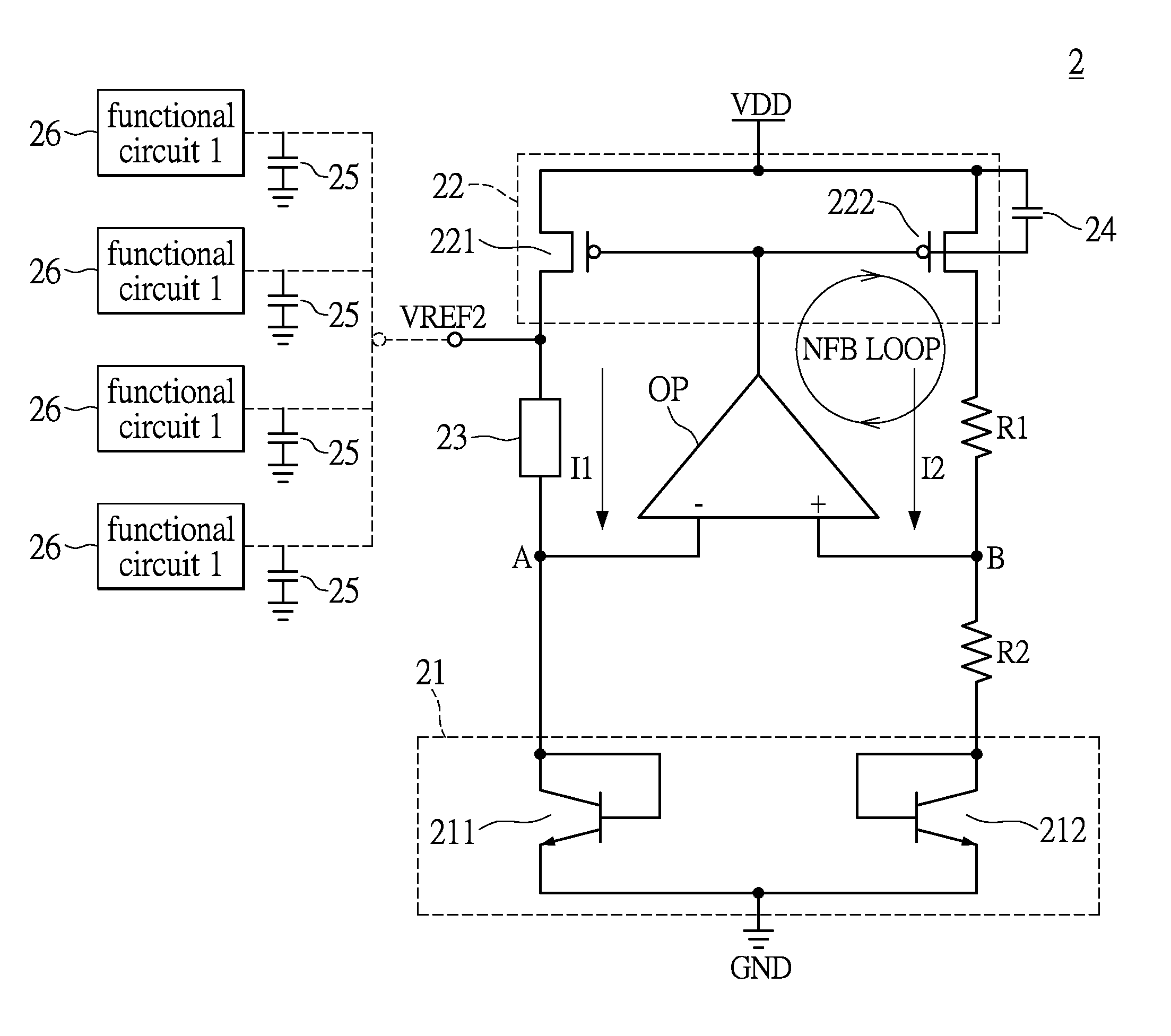
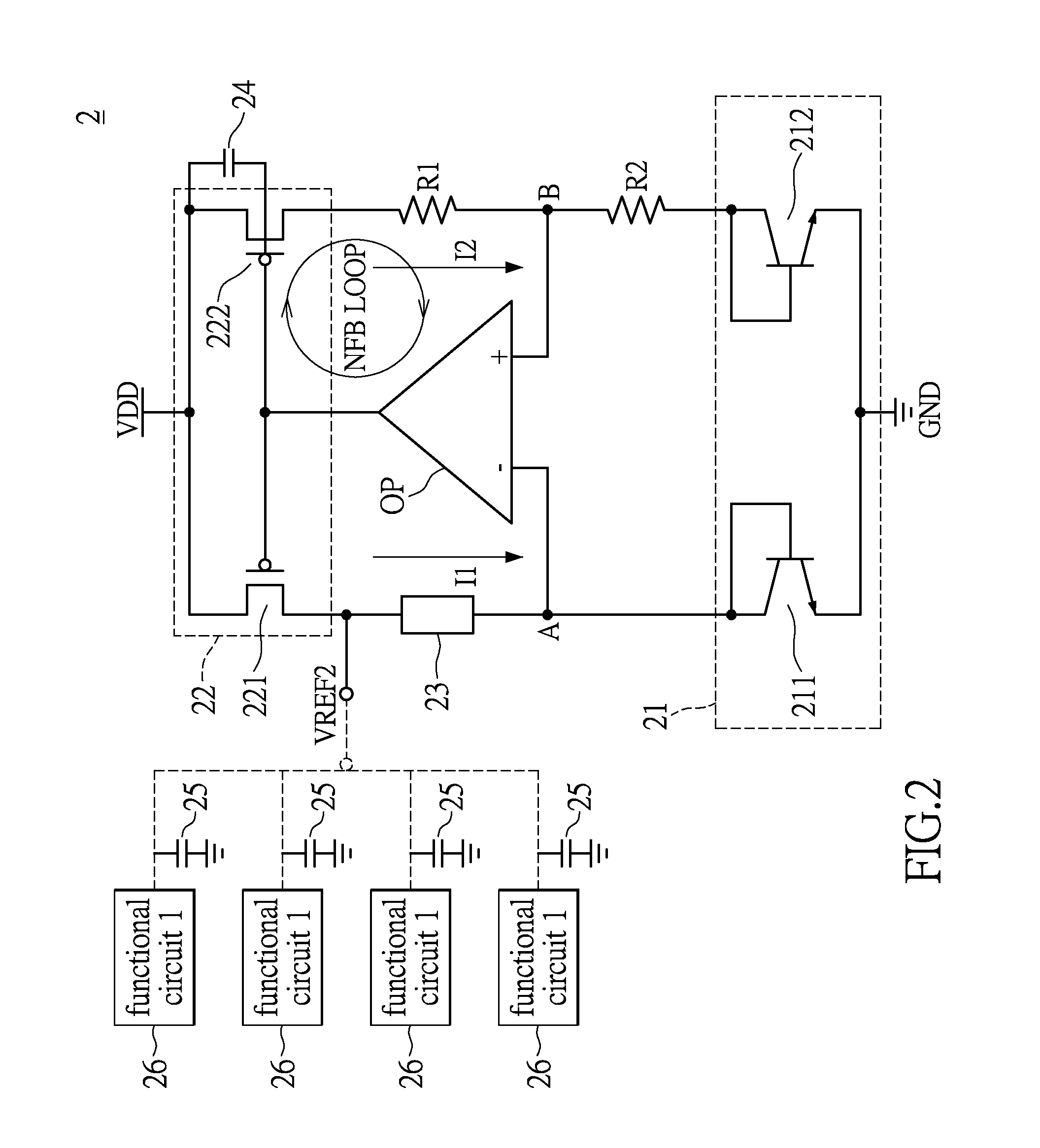
[0020]Please referring to FIG. 2, FIG. 2 shows a circuit diagram of a bandgap reference voltage circuit according to an embodiment of the present invention. A bandgap reference voltage circuit 2 comprises a current mirror unit 22, an operation amplifier OP, a voltage generation circuit 21, a first resistor R1, a second resistor R2, an auxiliary unit 23, a power supply VDD, ground GND and an output reference voltage port VREF2. An output end of the operation amplifier OP is coupled to a feedback end of the current mirror unit 22. An end of the first resistor R1 is coupled to a positive input end of the operation amplifier OP through the point B, another end of the first resistor R1 is couple


PUM


Abstract

A bandgap reference voltage circuit comprises a current mirror unit, an operation amplifier (OP), a first resistor, a second resistor, an auxiliary unit, and a voltage generation circuit. An output end of the OP is coupled to a feedback end of the current mirror unit. An end of the first resistor and an end of the second resistor are coupled to a positive input end of the OP. Another end of the first resistor is coupled to a second end of the current mirror unit. A second end of the voltage generation circuit is coupled to another end of the second resistor. An end of the auxiliary unit is coupled to a negative input end of the OP and a first end of the voltage generation circuit, and another end of the auxiliary unit is coupled to the first end of the current mirror unit.

Description


Claims


Application Information

Patent Timeline
Owner ILI TECHNOLOGY CORPORATION
Why Eureka
Try Eureka