Bicycle handlebar

a handlebar and bicycle technology, applied in the field of handlebars, can solve the problems of affecting the smoothness of turning made with the hands of the rider, and is easy to get out of control, and achieve the effect of avoiding hand sweating

Inactive Publication Date: 2015-05-14
TIEN HSIN INDS
View PDF5 Cites 4 Cited by
  • Summary
  • Abstract
  • Description
  • Claims
  • Application Information

AI Technical Summary

Benefits of technology

This patented technology solves problems when designing a bike's grip system by allowing riders to use their own body weight or other objects while still being able to control the direction they are facing during turns without slippage from traditional handles. A special surface called an Anti Slamming Plane (ASP) can be placed at this area where there was no longer any contact made after it turned around its center point. It prevents finger perspiration caused by rubbing against these surfaces instead of touching them directly.

Problems solved by technology

The technical problem addressed in this patents relates to improving the design of traditional bike handles used during mountain going activities such as walking up stairs without causing strain from prolonged use over longer periods.

Method used


Image

  • Bicycle handlebar
  • Bicycle handlebar
  • Bicycle handlebar

Examples


Embodiment Construction

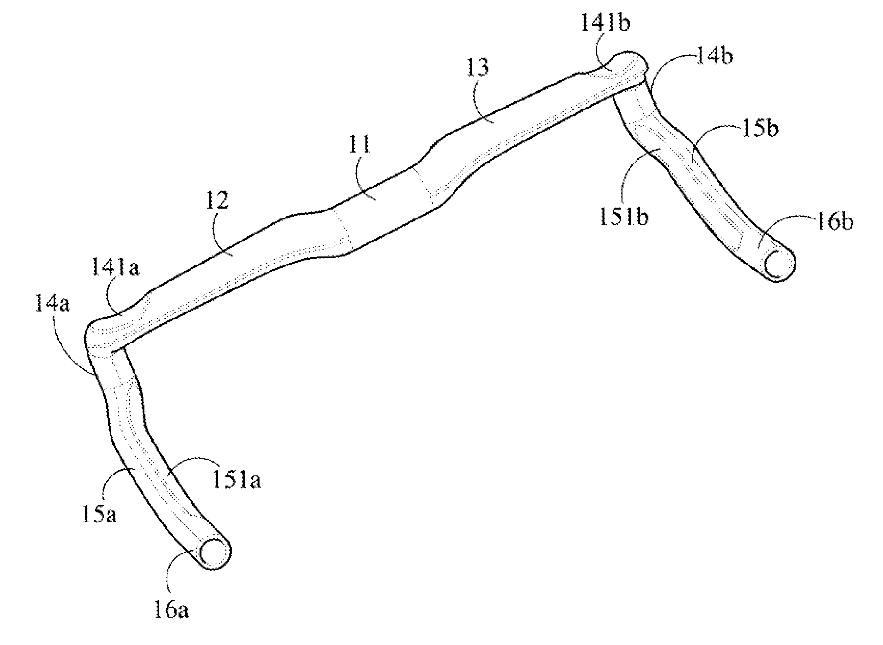
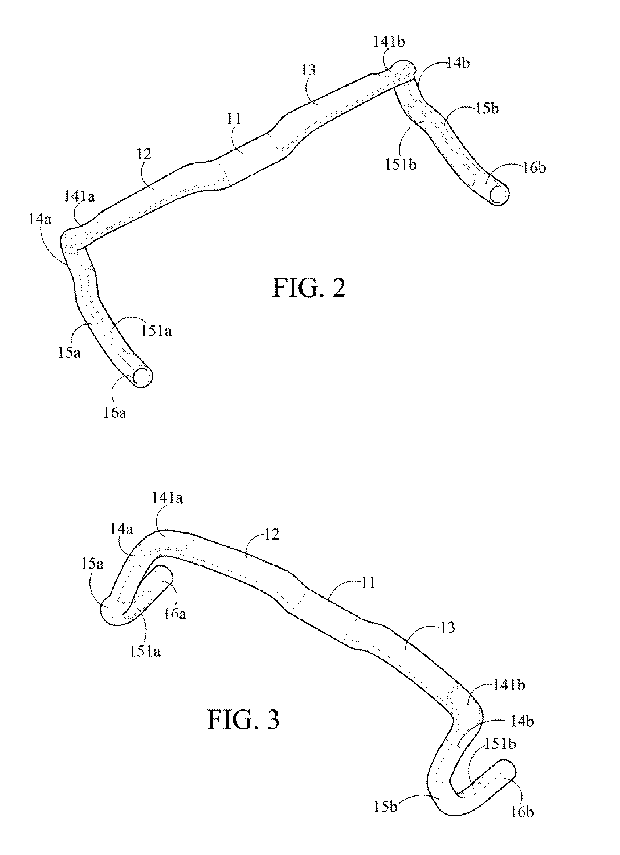
[0029]The detailed content and technical description of the present invention are further described through embodiments. Referring to FIG. 2, FIG. 3, FIG. 4A, FIG. 4B, and FIG. 5. FIG. 2 is a three-dimensional view of a first embodiment of the present invention. FIG. 3 is a three-dimensional view of the first embodiment of the present invention in another direction, FIG. 4A is a plane view of the first embodiment of the present invention. FIG. 4B is a partial enlarged view of FIG. 4A. FIG. 5 is a schematic view of a first use situation of the first embodiment of the present invention.

[0030]As shown in the figures, a bicycle handlebar of the present invention can be a hollow tube body made of a metal material, for example, an aluminum alloy, or a carbon fiber composite material. As shown in FIG. 2, the bicycle handlebar of a first embodiment of the present invention includes a main body 11, pivotally connected to a bicycle. A first holding portion 12 and a second holding portion 13 are


PUM


Abstract

A bicycle handlebar includes a main body pivotally connected to a bicycle. A first holding portion and a second holding portion corresponding to the first holding portion are disposed at left and right sides of the main body. The first holding portion and the second holding portion each bend towards a forward riding direction and extend to form a forward bending portion. The forward bending portions each extend towards a backward riding direction to form a backward bending portion. The backward bending portions each extend towards the backward riding direction to form a rear section. A distance between the two backward bending portions is greater than a distance between the two forward bending portions, so as to expand a turning radius of the bicycle handlebar.

Description


Claims


Application Information

Patent Timeline
Owner TIEN HSIN INDS
Why Eureka
Try Eureka