Method for building a three-dimensional model and apparatus thereof

Active Publication Date: 2015-05-21
INSTITUTE FOR INFORMATION INDUSTRY
View PDF2 Cites 21 Cited by
  • Summary
  • Abstract
  • Description
  • Claims
  • Application Information

AI Technical Summary

Benefits of technology

[0007]Accordingly, the present invention provides a method to build a 3D model of a physical object. The method uses depth information of images of the physical object to build an optimal camera path. Then, the 3D point clouds of all images are integrated together according to the optimal camera path. The 3D point clouds of all images are integrated together after the optimal camera path is built. Therefore, the method can solve the 3D model building fail because of the integrated error.

Problems solved by technology

Once a deviation occurs in calculating the rotation angle and the moving distance, the two adjacent images' 3D point clouds are unable to be integrated, which causes a failure in building the 3D model even with only a single calculation deviation.
That is, the calculation deviation accumulates and cannot be corrected in real time until the 3D model is finished, which causes a 3D model very different from the physical object.
Therefore, the method can solve the 3D model building fail because of the integrated error.
Therefore, the method can solve the problem of the 3D model building fail because of the integrated error.

Method used


Image

  • Method for building a three-dimensional model and apparatus thereof
  • Method for building a three-dimensional model and apparatus thereof
  • Method for building a three-dimensional model and apparatus thereof

Examples


Example

[0018]Specific embodiments of the invention are described in details as follows with reference to the accompanying drawings, wherein throughout the following description and drawings, the same reference numerals refer to the same or similar elements and are omitted when the same or similar elements are stated repeatedly.

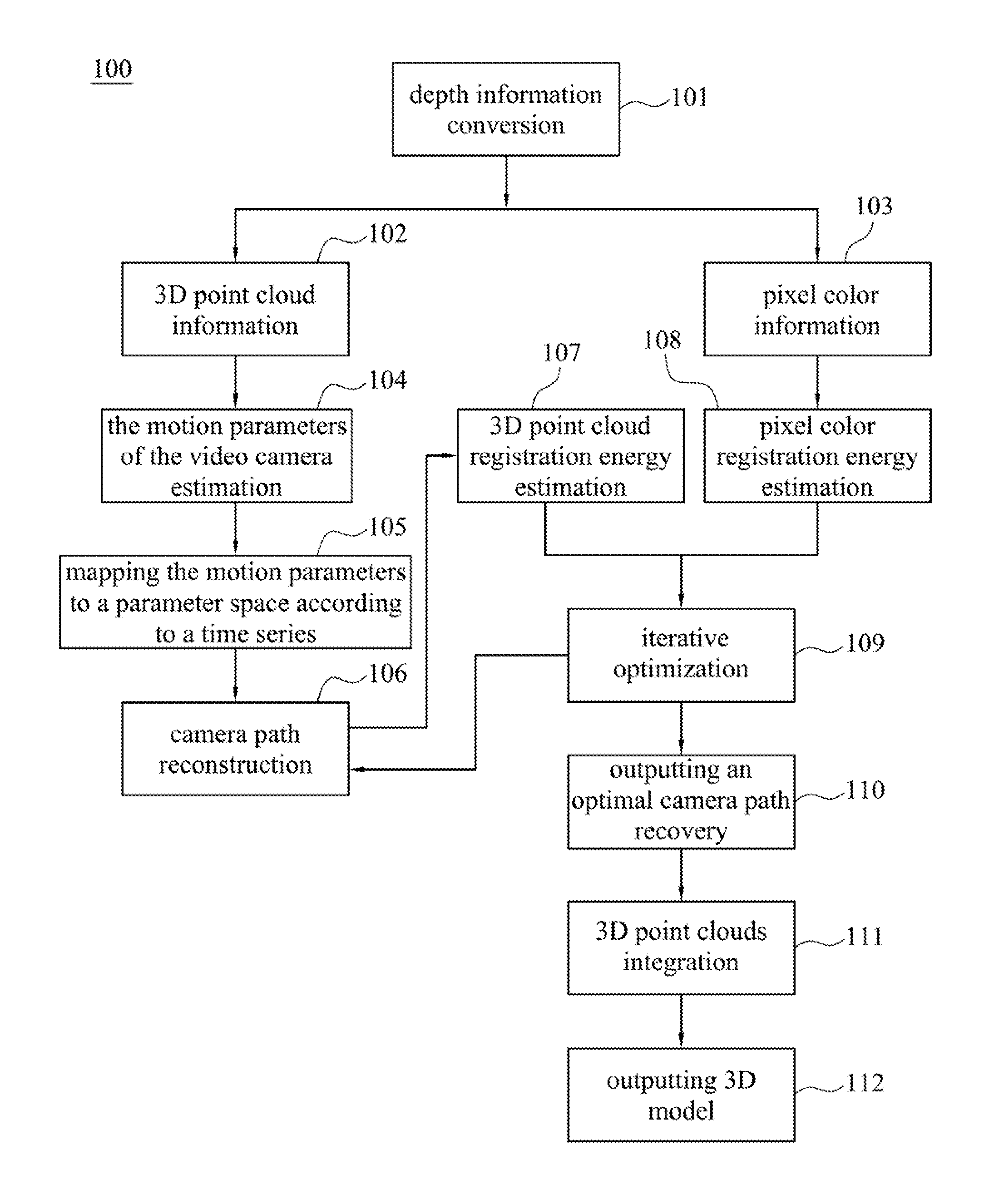
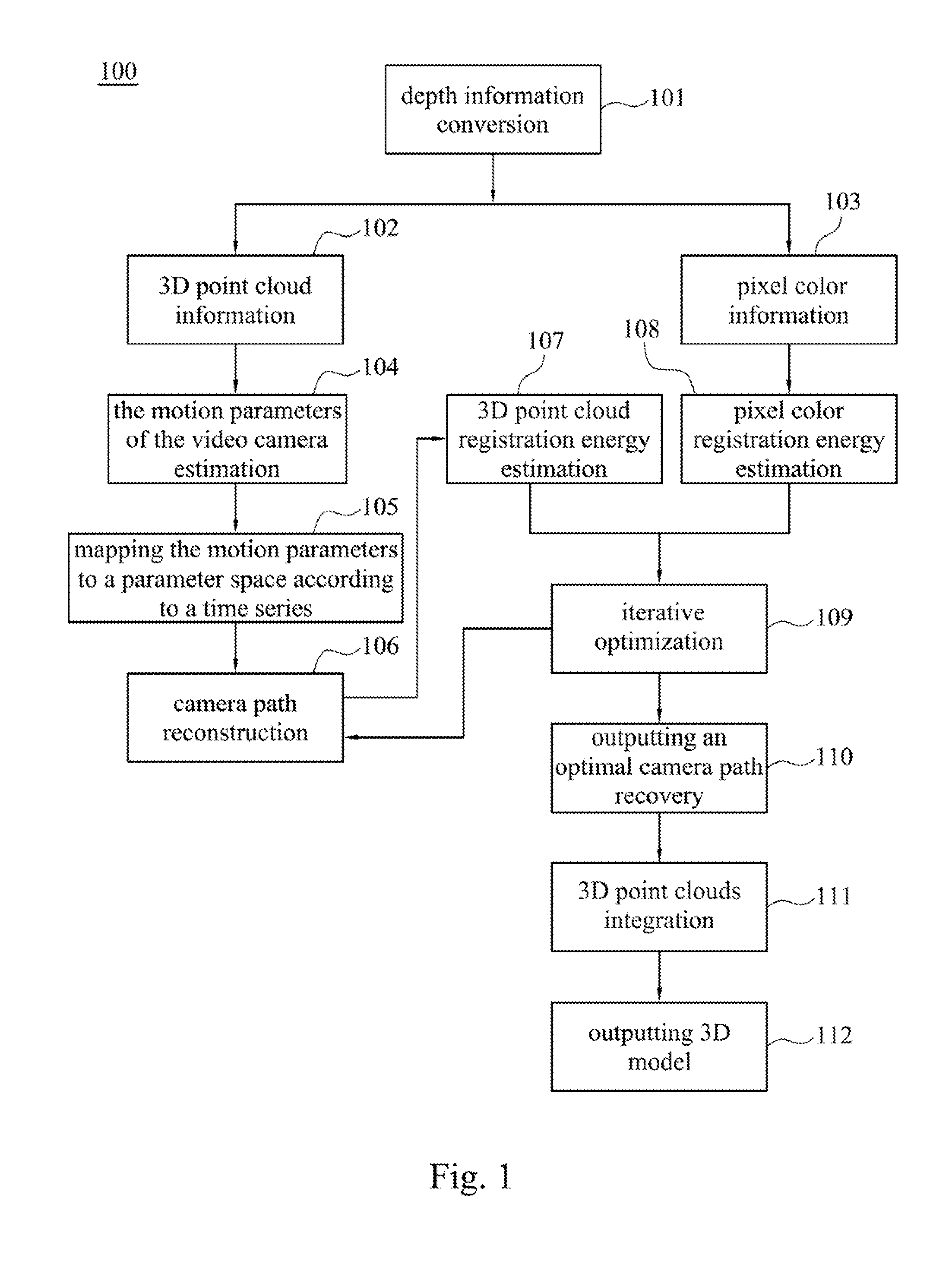
[0019]In the typical method, the present image's 3D point cloud is integrated into the previous image's 3D point cloud following the present image is gathered. That is, the wrong calculation result cannot be amended in real time. Therefore, the wrong calculation result is accumulated until the 3D model is finished, which will cause the final 3D model is very different from the physical object. Accordingly, for solving the above problem, the present image's 3D point cloud is not integrated into the previous image's 3D point cloud following the present image is gathered in the present invention. In contrast, after the video camera is positioned at different viewing angles


PUM


Abstract

A method to build a 3D model for a physical object includes the following steps. First, depth information of a plurality of images is converted into a plurality of 3D point clouds. Then, the motion parameters of the camera to gather each image relative to a previous image are determined according to the 3D point clouds. Next, a registration energy estimate value of each image's 3D point cloud, as being integrated into a previous image's 3D point cloud, is determined according to corresponding motion parameters. Then, the motion parameters are varied to minimize the estimate value. An optimal camera path is determined according to the varied motion parameters. Finally, a 3D model of the physical object is built according the optimal camera path.

Description


Claims


Application Information

Patent Timeline
Owner INSTITUTE FOR INFORMATION INDUSTRY
Why Eureka
Try Eureka