Adaptor Tee

Inactive Publication Date: 2015-06-18
SIEMENS AG
View PDF13 Cites 0 Cited by
  • Summary
  • Abstract
  • Description
  • Claims
  • Application Information

AI Technical Summary

Benefits of technology

[0020]In an embodiment, the inlet connection and the second outlet connection are female connections (e.g., female connections having an inner thread). The permeate outlet port and the end of the conduit for collecting the permeate may then be provided with male connections having outer threads, thus enabling a relatively simple assembly.
[0021]In an embodiment, the main body has a cylindrical section of reduced diameter adjacent to the second end. The cylindrical section of reduced diameter provides the first outlet connection. The first outlet connection is a male connection having an outer thread on the cylindrical section of reduced diameter. Attachment of a sample valve to such type of connection may be facilitated.
[0022]In an embodiment, the main body has a first cylindrical section having a first outer diameter and a second cylindrical section having a second outer diameter. The first diameter is larger than the second diameter. The main body may further have a third cylindrical section having an outer diameter similar to the second outer diameter. The first cylindrical section is located between the second end and the third cylindrical sections. A compact and low weight but strong design of the adaptor tee may thus be achieved.

Problems solved by technology

A problem occurring with such fittings is that the material has a relatively low UV-resistance.
Further, the pressure to which such standard fittings may be exposed is relatively limited.
The pressure rating may not be suitable for oil and gas applications (e.g., offshore applications).
Also, to provide such different connections, standard fittings include several pieces mounted together, resulting in an increased risk of leakage.
Such fittings would result in a significantly increased weight, and would furthermore result in a very expensive solution.
Also, the risk of leakage due to the several pieces used remains.

Method used


Image

  • Adaptor Tee
  • Adaptor Tee
  • Adaptor Tee

Examples


Example

[0043]Embodiments will be described in detail with reference to the accompanying drawings. The following description of the embodiments is given only for the purpose of illustration and is not to be taken in a limiting sense.

[0044]The drawings are to be regarded as being schematic representations only, and elements in the drawings are not necessarily to scale with each other. Rather, the representation of the various elements is chosen such that their function and general purpose become apparent to a person skilled in the art.

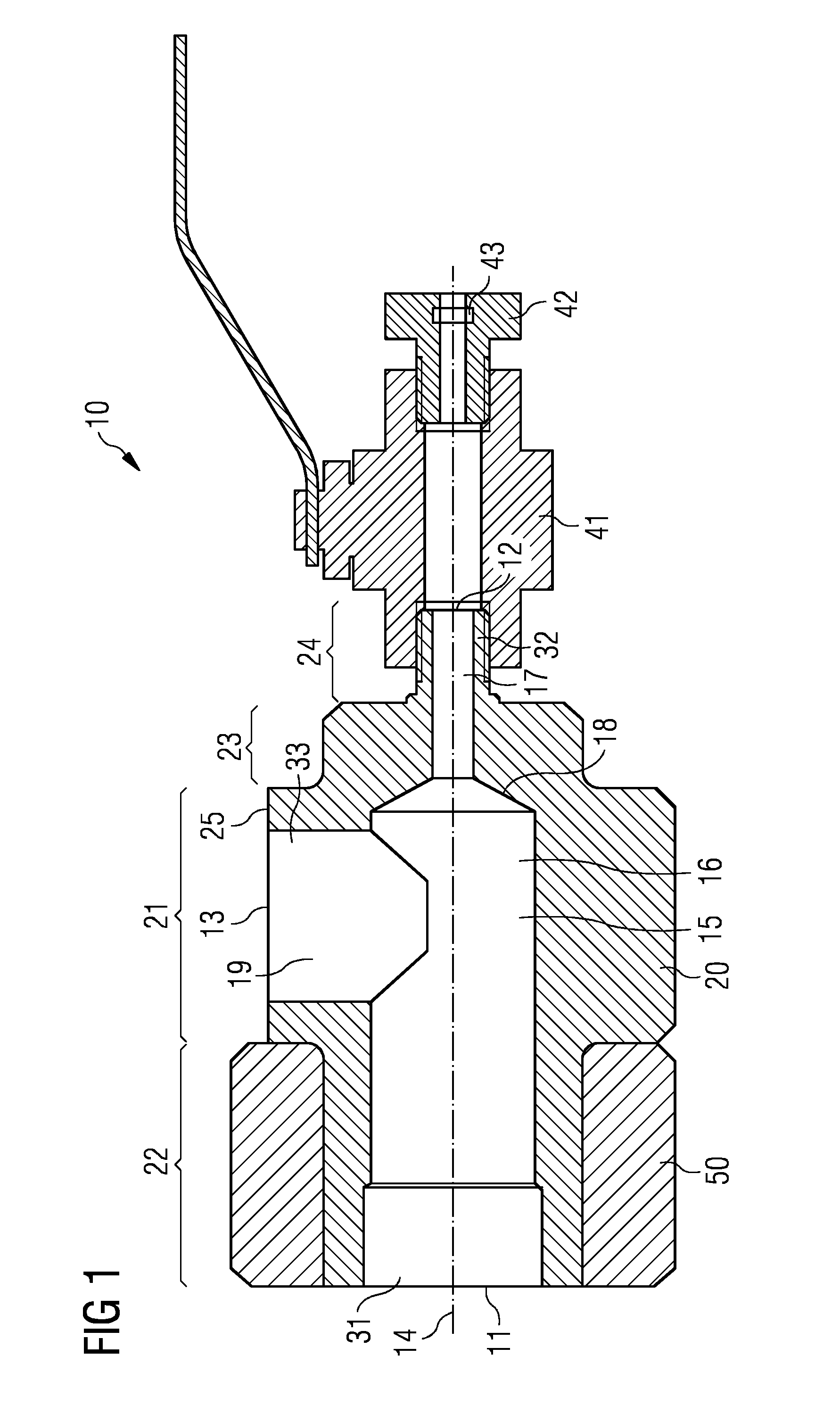
[0045]FIG. 1 is a schematic drawing showing a sectional side view of an adaptor tee 10 according to an embodiment. The adaptor tee 10 includes a main body 20 that is made of a single piece of plastic material. The main body 20 has a cylindrical shape that extends along the axial direction or longitudinal axis 14. At a first end, the main body 20 has a first inlet opening 11. At a second opposite end, the main body 20 has a first outlet opening 12. Between the inle


PUM

PropertyMeasurementUnit
Flow rateaaaaaaaaaa
Diameteraaaaaaaaaa
Molecular weightaaaaaaaaaa

Abstract

An adaptor tee for a filtration system, in particular for the permeate outlet port of a filtration vessel is provided. The adaptor tee has a main body of a single piece of plastic material having a cylindrical shape extending along an axial direction between opposing first and second ends. An inlet opening is provided in the first end of the main body for connecting the adaptor tee to a permeate outlet port of a filtration vessel. A first outlet opening is provided in the second end of the main body for connecting a sample valve. A first flow passage extends through the main body between the inlet opening and the first outlet opening. Furthermore, a second outlet opening through the lateral surface of the main body for a connection to a collection conduit is provided. A second flow passage extends through the main body between the first flow passage and the second outlet opening. The second flow passage meets the first flow passage in a T-junction.

Description


Claims


Application Information

Patent Timeline
Owner SIEMENS AG
Why Eureka
Try Eureka