Smart head-mounted projection system

a projection system and head-mounted technology, applied in the field of projection systems, can solve the problems of limiting the individual's ability to have a personalized or private experience, reducing the user's enjoyment of the experience, etc., and achieve the effect of accurately determining the distance between the screen finger z

Active Publication Date: 2015-10-01
SMITS GERARD DIRK
View PDF8 Cites 16 Cited by
  • Summary
  • Abstract
  • Description
  • Claims
  • Application Information

AI Technical Summary

Benefits of technology

The technical effect of this patented technology is how it allows users to see their own images from different angles while also having them interact with each others through special techniques like triangulation or stereo observation. Additionally, there is another option where an auxiliary screen provides added capabilities such as selecting specific colors or adding stickers to create more immersive experiences.

Problems solved by technology

The technical problem addressed by this patent is how to create a 3D display system where individuals can interact with each other without being restricted from moving around within it due to the movements caused by the users themselves.

Method used


Image

  • Smart head-mounted projection system
  • Smart head-mounted projection system
  • Smart head-mounted projection system

Examples


Embodiment Construction

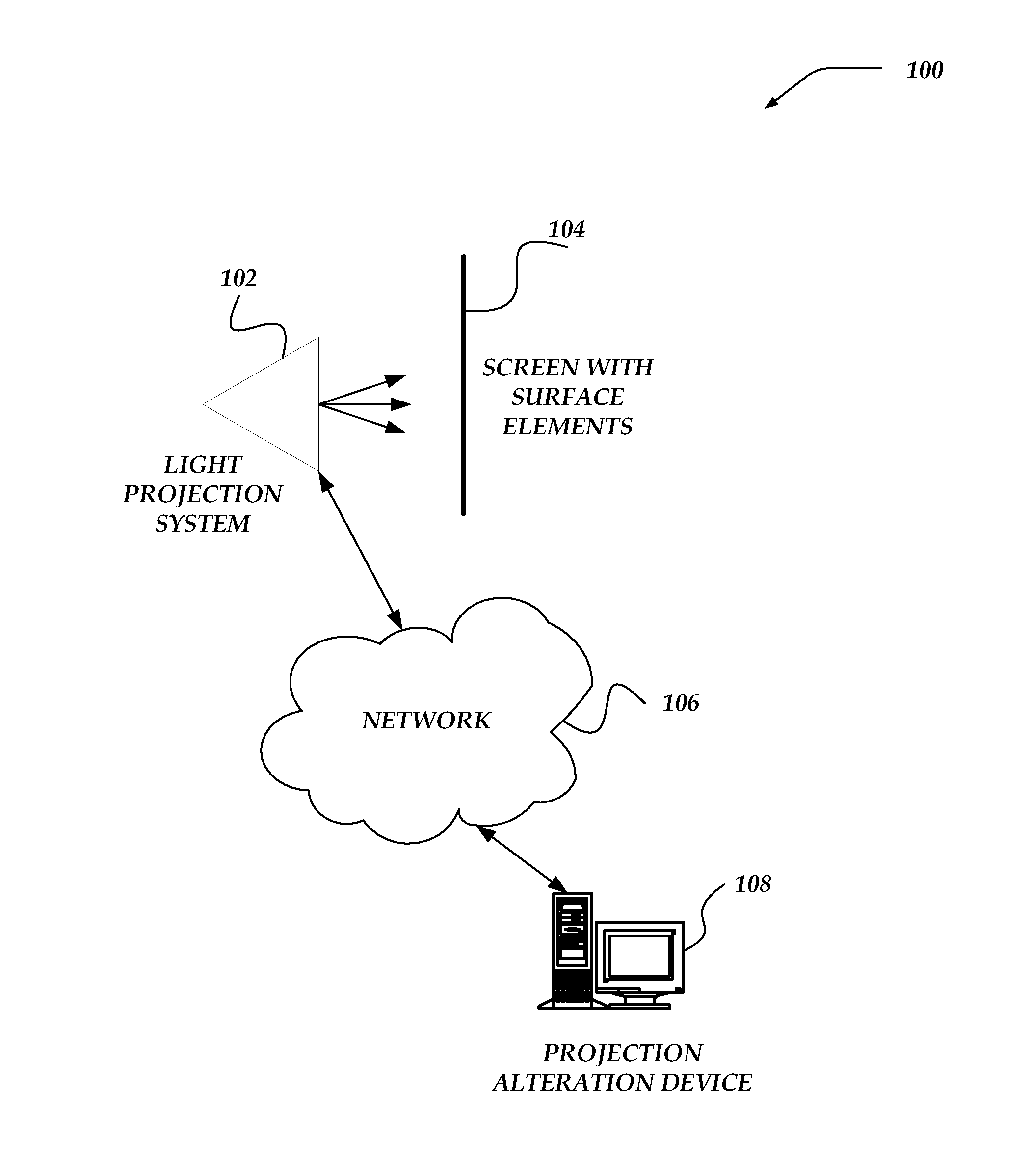
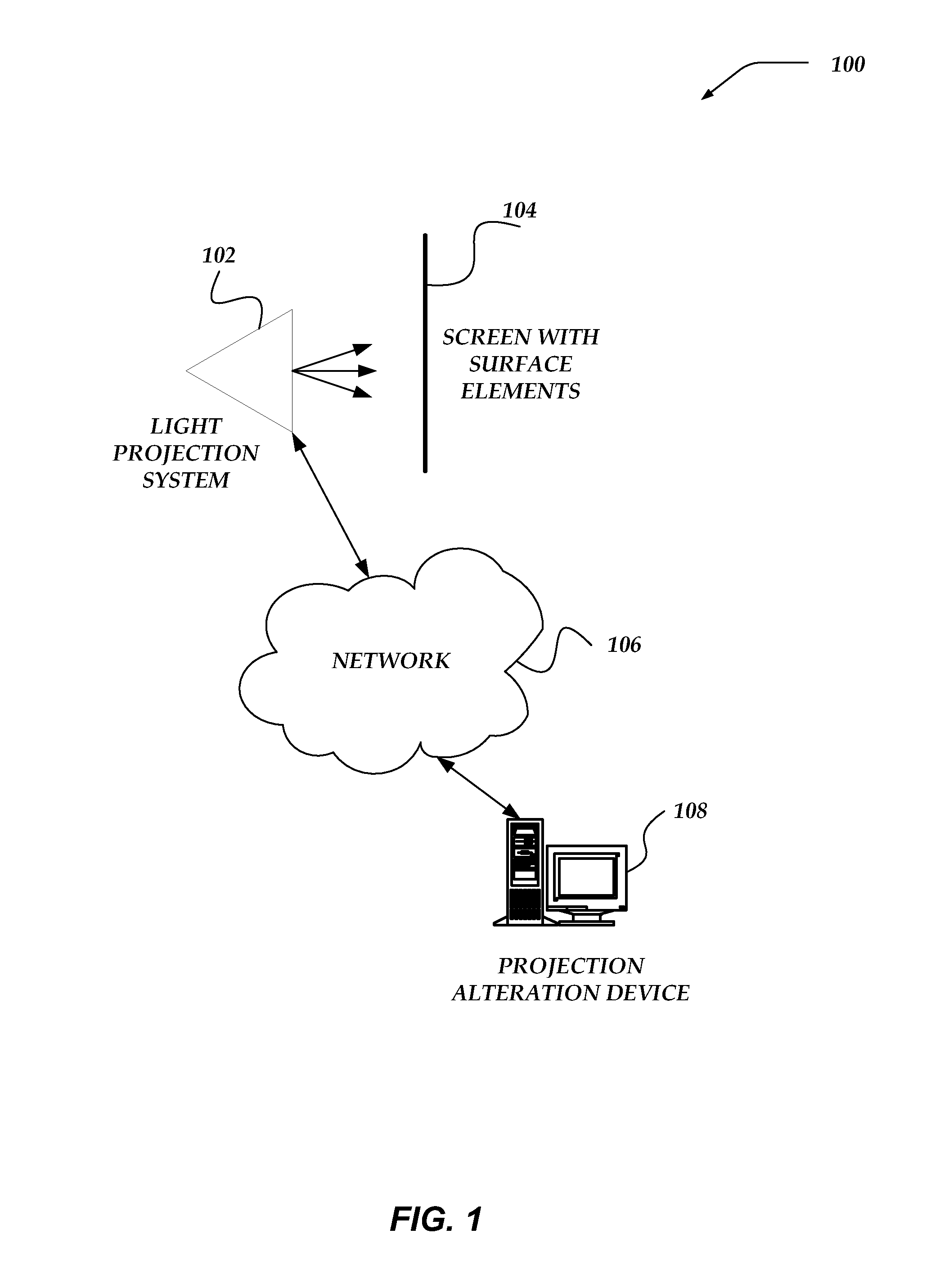
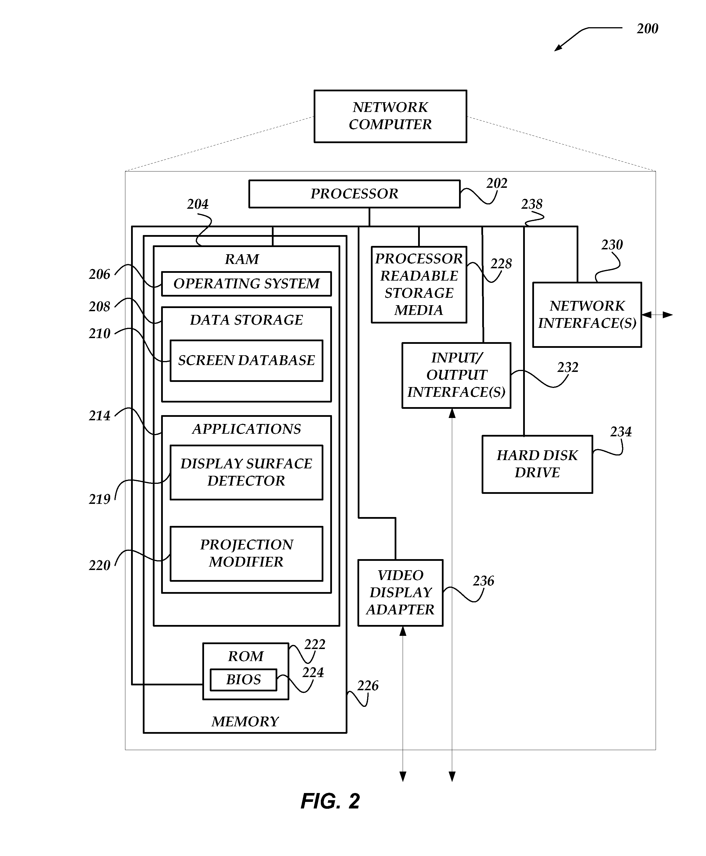
[0018]Various embodiments now will be described more fully hereinafter with reference to the accompanying drawings, which form a part hereof, and which show, by way of illustration, specific embodiments by which the invention may be practiced. The embodiments may, however, be embodied in many different forms and should not be construed as limited to the embodiments set forth herein; rather, these embodiments are provided so that this disclosure will be thorough and complete, and will fully convey the scope of the embodiments to those skilled in the art. Among other things, the various embodiments may be methods, systems, media, or devices. Accordingly, the various embodiments may take the form of an entirely hardware embodiment, an entirely software embodiment, or an embodiment combining software and hardware aspects. The following detailed description is, therefore, not to be taken in a limiting sense.

[0019]Throughout the specification and claims, the following terms take the meanings


PUM


Abstract

Embodiments are directed towards a system for enabling a user to view an image on a surface. The system may include projector(s), sensor, projection surface or screen, and processor. The projectors may project light for an image onto the surface. The sensor may detect light reflected off the surface. The surface may include multiple types of surface elements, such as multiple first elements positioned as border of a display area on the surface to provide feedback regarding the surface and multiple second elements positioned within the border of the display area to reflect the image to the user. The processor may determine characteristics of the border of the display area based on light reflected to the sensor from first elements. And it may modify parameters of the image based on the characteristics of the border of the display area.

Description


Claims


Application Information

Patent Timeline
Owner SMITS GERARD DIRK
Why Eureka
Try Eureka