Eddy current mold level measuring device and mold level measuring method

a level measuring device and mold technology, applied in the direction of liquid/fluent solid measurement, volume measurement, instruments, etc., can solve the problems of inability to adapt, insufficient accuracy of above-described methods, and the inability to improve the accuracy of measuring devices, etc., to achieve the effect of ensuring the accuracy of the measurement devi

Inactive Publication Date: 2016-02-04
NIRECO CORP
View PDF0 Cites 0 Cited by
  • Summary
  • Abstract
  • Description
  • Claims
  • Application Information

AI Technical Summary

Benefits of technology

The inventive method allows for continuously castings with multiple changes over time without any significant issues like changing or shifting material levels during production. This makes it suitable for various types of dynamics that can affect product quality.

Problems solved by technology

This technical problem addressed in this patents relates to accurately determining the height or depth of a specific area within a cast product's interior without affecting its environment during manufacture. Current techniques involve manual adjustment with reference levels from time series data collected through magnetic induction loops, which require precise placement at different locations along the length of the production line. Additionally, these systems often rely upon external factors such as environmental influences caused by heat waves and electric fields, making it difficult to ensure accurate results even if they were initially set up correctly over long periods of operation due to variations in surrounding environments.

Method used


Image

  • Eddy current mold level measuring device and mold level measuring method
  • Eddy current mold level measuring device and mold level measuring method
  • Eddy current mold level measuring device and mold level measuring method

Examples


Embodiment Construction

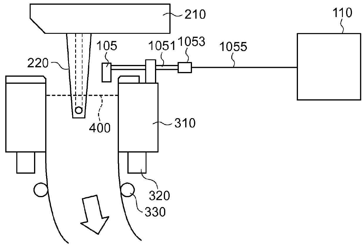
[0046]FIG. 1 shows an arrangement of continuous casting equipment.

[0047]Molten metal such as molten steel stored in a tundish 210 is poured into a mold 310 through an immersion nozzle 220, made to solidify in the mold 310 and delivered from the mold 310 through the use of pinch rolls 330. Further, the mold 310 is equipped with a mold oscillation device 320. Mold oscillation will be described later.

[0048]When in a certain time period an amount of molten metal which is poured into the mold 310 is greater than an amount of metal which is delivered from the mold 310, a level of a surface 400 of the molten metal in the mold 310 goes up. On the other hand, when in a certain time period an amount of metal which is delivered from the mold 310 is greater than an amount of molten metal which is poured into the mold 310, the level of the surface 400 of the molten metal in the mold 310 goes down. Under the above-described situation, an eddy current mold level measuring device according to an embod


PUM

PropertyMeasurementUnit
Timeaaaaaaaaaa
Ratioaaaaaaaaaa
Levelaaaaaaaaaa

Abstract

The measuring device includes: a detecting section including a coil which detects a change in a value of impedance caused by a change in a mold level; an amplifying section which amplifies an output of the detecting section; a pre-pouring calibration section which determines a reference value of a positive feedback ratio of the amplifying section in environmental conditions before pouring of molten metal; and a mold oscillation signal calibration section which obtains a standard value of difference in an output of the measuring device, the standard value of difference corresponding to a known value of amplitude of mold oscillation when the positive feedback ratio is the reference value, obtains a deviation of measurement based on a difference between the maximum value and the minimum value of the output in mold oscillation and the standard value, and corrects the positive feedback ratio within a predetermined range including the reference value.

Description


Claims


Application Information

Patent Timeline
Owner NIRECO CORP
Why Eureka
Try Eureka