Protection arrangement for an electric vehicle

Active Publication Date: 2016-05-12
VOLVO LASTVAGNAR AB
View PDF3 Cites 14 Cited by
  • Summary
  • Abstract
  • Description
  • Claims
  • Application Information

AI Technical Summary

Benefits of technology

[0012]By this first embodiment of the protection arrangement for a current collector according to the invention, the protection arrangement will be opened automatically when the vehicle arrives at or has reached a charging position such that contact between the current collector and a corresponding current supply means is possible during charging of the electric energy storage of the vehicle. The rechargeable electric energy storage may be a battery or a super capacitor. When the electric energy storage is not charged, e.g. when the vehicle is not positioned at a charging station, the current collector will be covered by the protection arrangement. In this way, an accidental contact with the current collector by a service person will not be possible. It is of advantage that the protection arrangement is enclosed such that an operator can not touch the current collector. Preferably, the protection arrangement will stop an arm or a finger from passing through, and also a pointed object such as a screwdriver or the like such that maintenance can be performed close to the protection arrangement without the risk of touching the current collector. It is also an advantage to enclose the current collector in case of an accident, e.g. when the vehicle falls over on the side. The rescue party will be able to start working without the risk of touching the current collector and will not have to start by disabling the current collector before they can proceed. An enclosed current collector is also a security advantage should someone unauthorized climb up on the roof of the vehicle.
[0013]It is further advantageous to automatically open the protection arrangement when the vehicle reaches a predefined charging position. In this way, the current collector will be enclosed when the vehicle e.g. is travelling or is parked outside of the charging station. When the vehicle is at the charging station, in the predefined charging position, the protection arrangement can be opened automatically. The protection arrangement can e.g. be opened automatically when the vehicle enters a predefined charging area such that the protection arrangement is open when the vehicle stops at the chargi

Problems solved by technology

This also means a corresponding increase in the need to charge such vehicles.
Such vehicles are referred to as plug-in vehicles and are common for hybrid vehicles which are provided with a battery having a relatively low capacity, such that the distance that the vehicle can travel on electric power is limited.
For vehicles that need to be charged several times a day, such as commercial vehicles, a connection by using a plug is not an efficient alternative.
Such a switch is rather expensive.
They may work fine in some situations, but a

Method used


Image

  • Protection arrangement for an electric vehicle
  • Protection arrangement for an electric vehicle
  • Protection arrangement for an electric vehicle

Examples


first embodiment

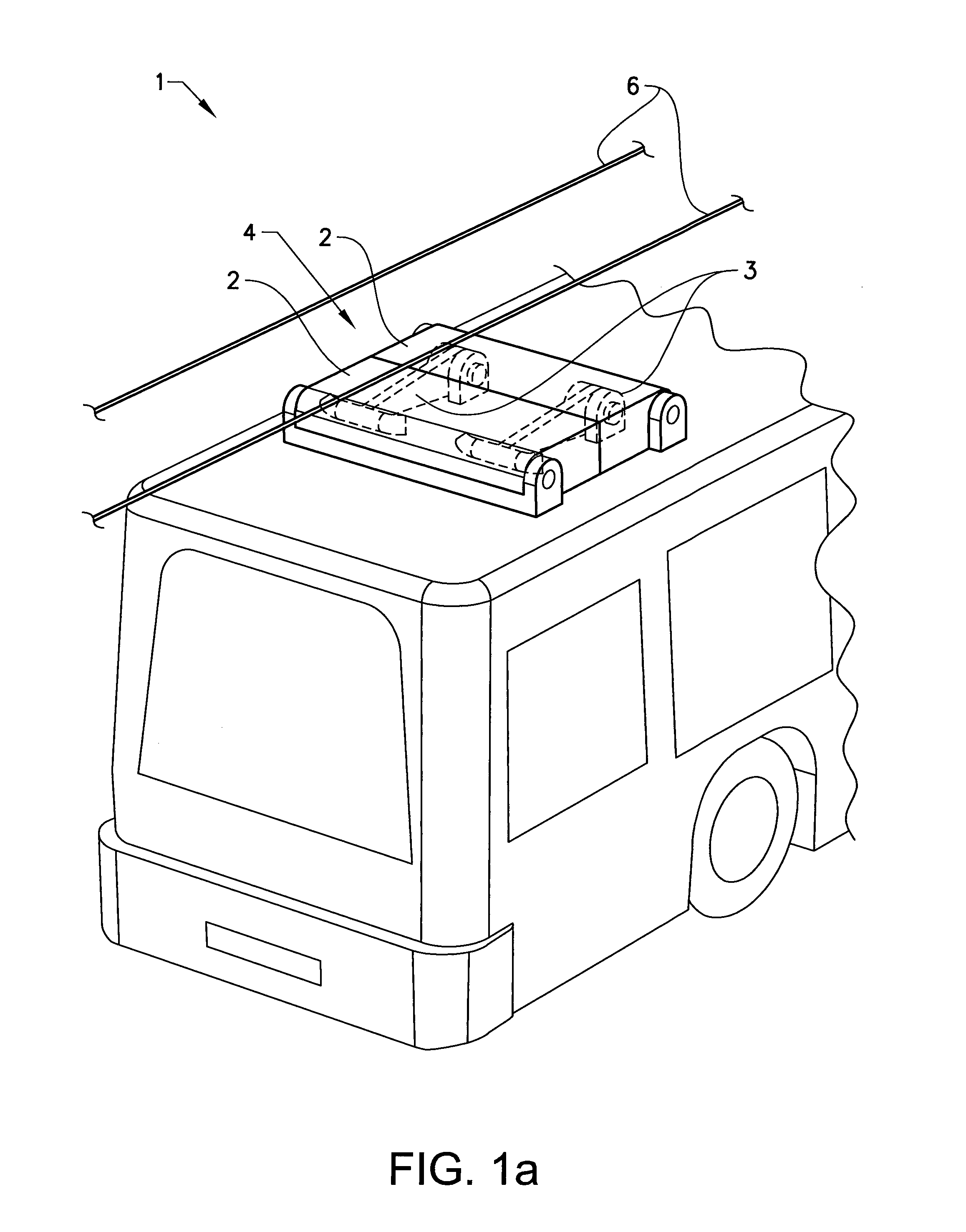
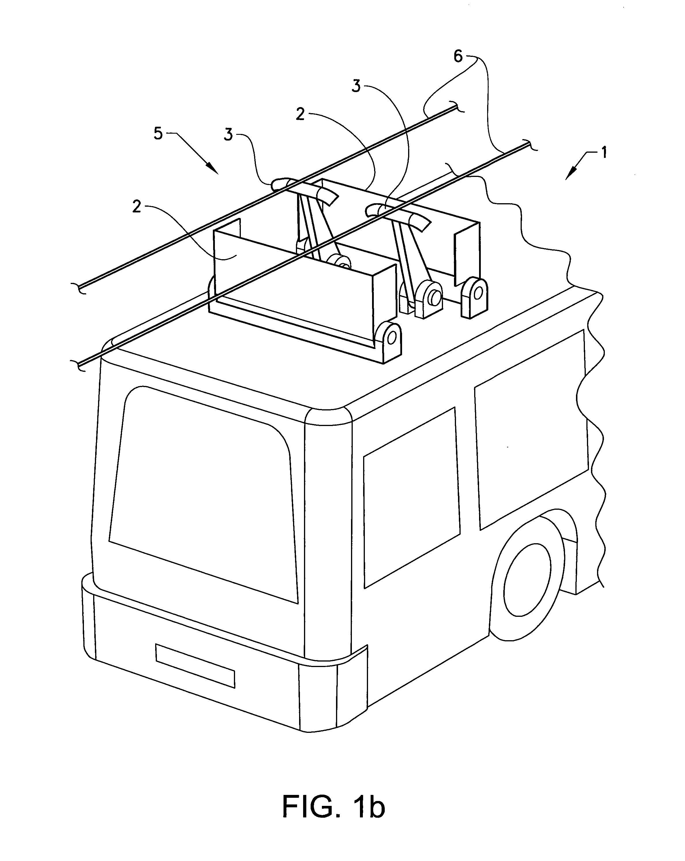
[0032]FIG. 1a and b shows a schematic first embodiment of a protection arrangement for a current collector according to the invention. In this embodiment, the current collector 3 is a pantograph and the protection arrangement 1 comprises two pivotable covers 2. The pantograph is used to connect an external current source to a rechargeable energy source, such as a battery or super capacitor, installed in the electric vehicle. The pantograph is preferably mounted on the roof of the vehicle, but it would also be possible to mount it under the vehicle such that it folds down towards a conductor rail below the vehicle. In the shown example, the pantograph folds up towards a conductor line 6 or conductor surface positioned above the vehicle, somewhat similar to the pantograph used by trams or trains. However, the mechanical design is less demanding since the pantograph will only be used for charging the vehicle battery when the vehicle is stationary, i.e. when the vehicle stands still at the

second embodiment

[0034]FIGS. 2 to 4 show a schematic second embodiment of a protection arrangement for a current collector according to the invention. In this embodiment, the current collector 10 is a fixed contact surface mounted on the roof of a vehicle and the protection arrangement 1 comprises a movable cover, in the first example a slideable cover 11. The contact surface is used to connect an external current source to a battery installed in the electric vehicle. The contact surface is preferably mounted on the roof of the vehicle, but it would also be possible to mount it under the vehicle. The contact surface is adapted to be contacted to a current supply means that will approach the contact surface when the vehicle is at the charging position at the charging station. The current supply means may be spring-loaded. The contact surface preferably extends somewhat from the roof of the vehicle.

[0035]The current supply means is mounted at the charging station. The current supply means may be a fixed


PUM


Abstract

A protection arrangement for a current collector arranged on a vehicle having a rechargeable energy storage includes a first protective state in which the current collector is covered by the protection arrangement and a second open state in which the protection arrangement allows contact between the current collector and a corresponding current supply during charging of the energy storage and where the protection arrangement is automatically opened from the protective state to the open state when the vehicle has reached a predefined charging position. The current collector can be enclosed when the vehicle is not charged and the protection arrangement can open automatically when a charging position is reached. This can improve the safety of the vehicle and obviate the need of a specific circuit breaker that can disconnect the current collector from the electric energy storage. The charging of the vehicle can also be simplified.

Description


Claims


Application Information

Patent Timeline
Owner VOLVO LASTVAGNAR AB
Why Eureka
Try Eureka