Feet positioning system for magnetic resonance imaging studies
a magnetic resonance imaging and positioning system technology, applied in the field of human medicine, can solve the problems of insufficient methods of diagnosis of foot diseases and the lower parts of the legs, uncertain diagnosis of mri, and insufficient foot studies with images, and achieve the effect of resisting frequent cleaning and disinfection
- Summary
- Abstract
- Description
- Claims
- Application Information
AI Technical Summary
Benefits of technology
Problems solved by technology
Method used
Image


Examples
example 1
Positioning of the Individual
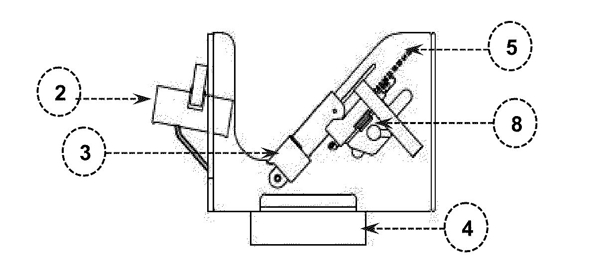
[0039]The first step to ensure reproducibility of quantitative measurements for the scan of MRI was to correctly position both feet and legs of the individual in the device shown in FIG. 1, coupled to the RF coil of the MRI equipment. The individual lays face up (supine) in the equipment bed with his legs towards the entrance of the magnetic system, as illustrated in FIG. 5.
[0040]The feet and the lower parts of the legs were placed and fixed, to obtain simultaneously MRI (e.g., coronal and axial sections) and Magnetic Resonance Spectra (MRS) of both feet, without changing the position. This allowed us to compare, on an equal condition, both limbs along the studies, and so that a lower member serves as reference to the other one.
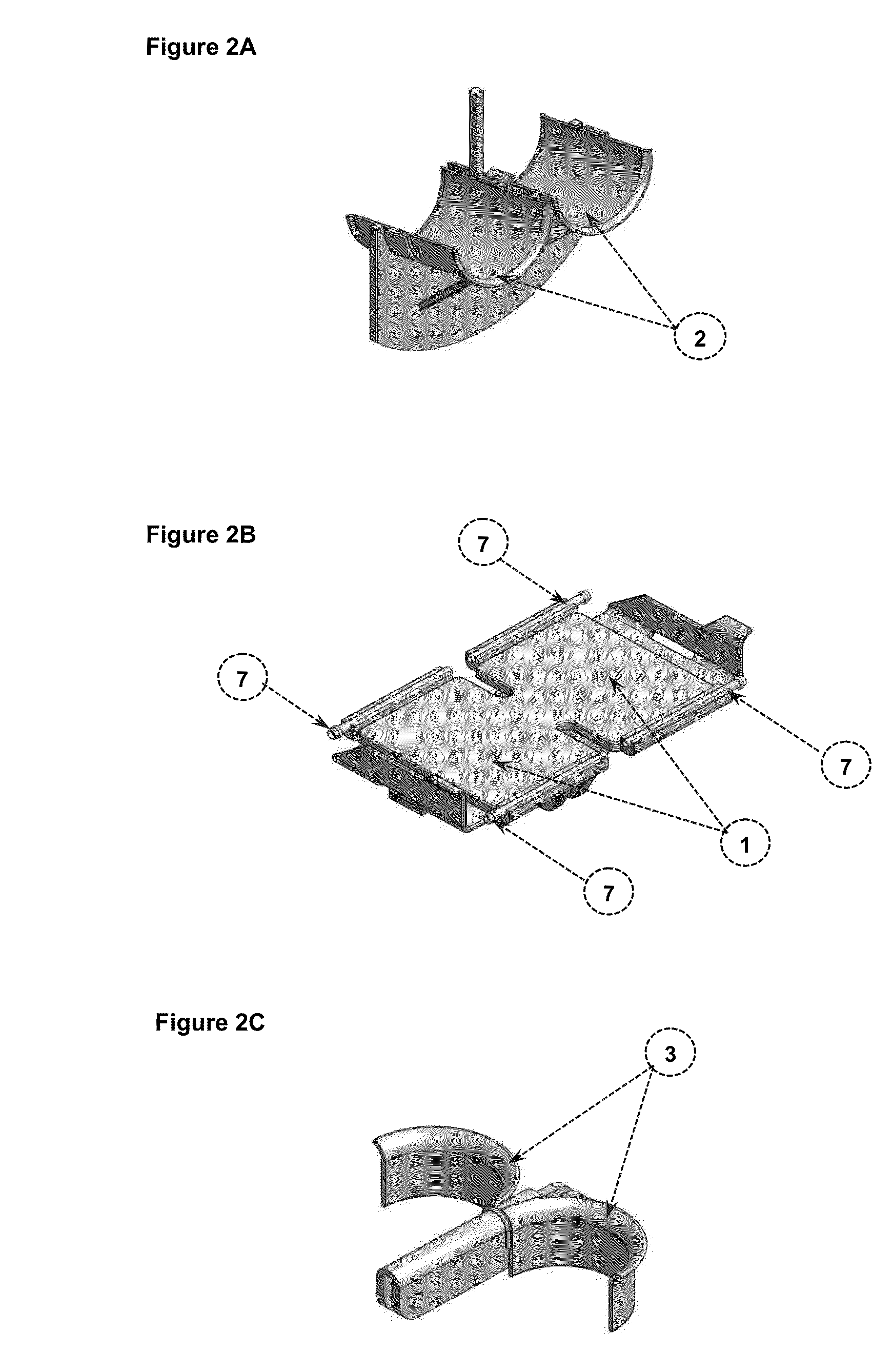
[0041]Each foot carefully rested on the support surfaces 1 and heels were leaned on arches 3. At unison, the lower parts of the legs were supported on supports 2, which were conveniently fitted with pins 8, according to the dimension
example 2
Checking and / or Correction of the Position of the Feet
[0043]Once positioned the feet of the individual, he was placed at the isocenter of the magnet system, and proceeded to record the planning MRI in three sections: coronal, sagittal and axial. The MRI showed the external markers 7. The correct position of the feet was checked, so that the MRI of soles appeared fully supported on the support surfaces 1, determined by the pairs of external markers 7 for each foot. In case the positioning was not correct, it was corrected as in Example 1. If the positioning was correct, the final planning of study sections proceeded.
example 3
Planning and Orientation of the Sections
[0044]The first section to be recorded was oriented parallel to the plane determined by the external markers, although it could be any plane, according to a preset angle in reference to the one determined by such markers. Other necessary sections were determined in connection with this first one, according to the study to be performed.
[0045]In FIG. 6 is shown the orientation of the sections planned and applied in Examples 4 to 10. The coronal section (FIG. 6A) is taken parallel to the plane determined by the external markers, and the other two sections (sagittal, FIG. 6B and axial, FIG. 6C) are orthogonal to the initial coronal section.
PUM
 Abstract
Description
Claims
Application Information
 - R&D Engineer
- R&D Manager
- IP Professional
- Industry Leading Data Capabilities
- Powerful AI technology
- Patent DNA Extraction
Browse by: Latest US Patents, China's latest patents, Technical Efficacy Thesaurus, Application Domain, Technology Topic.
© 2024 PatSnap. All rights reserved.Legal|Privacy policy|Modern Slavery Act Transparency Statement|Sitemap