Hip joint dislocation gypsum reduction supporting device

A support device and hip joint technology, applied in the field of medical equipment, can solve the problems of high work intensity and difficulty for doctors, and achieve the effect of simple structure, convenient operation and comfortable use

Pending Publication Date: 2021-07-09
昆明市儿童医院
View PDF0 Cites 0 Cited by
  • Summary
  • Abstract
  • Description
  • Claims
  • Application Information

AI Technical Summary

Benefits of technology

This patented technology allows for carrying both the lower part (the baby) from its mother while still being protected during examination or treatment. It also includes features like an ankybath that blocks off excess moisture when the patient lies down without getting wet due to their legs. Additionally, there are feet attached to these supports with screw threads instead of nails, making them easier to install and remove once they have been used again. Overall, this innovation makes healthcare providers more comfortable at home and reduces workload compared to traditional methods such as wrapping paper around the infant's leg before taking caregivers up.

Problems solved by technology

Technological Problem addressed in this patents are how to prevent inherited dislocations from developing between different parts of the body when they happen due to genetic factors like autism spectrum syndrome. Current methods involve fixing fractures with external devices such as splints or braces during therapy, while still allowing some movement even if it happens again later.

Method used


Image

  • Hip joint dislocation gypsum reduction supporting device
  • Hip joint dislocation gypsum reduction supporting device
  • Hip joint dislocation gypsum reduction supporting device

Examples


Embodiment 1

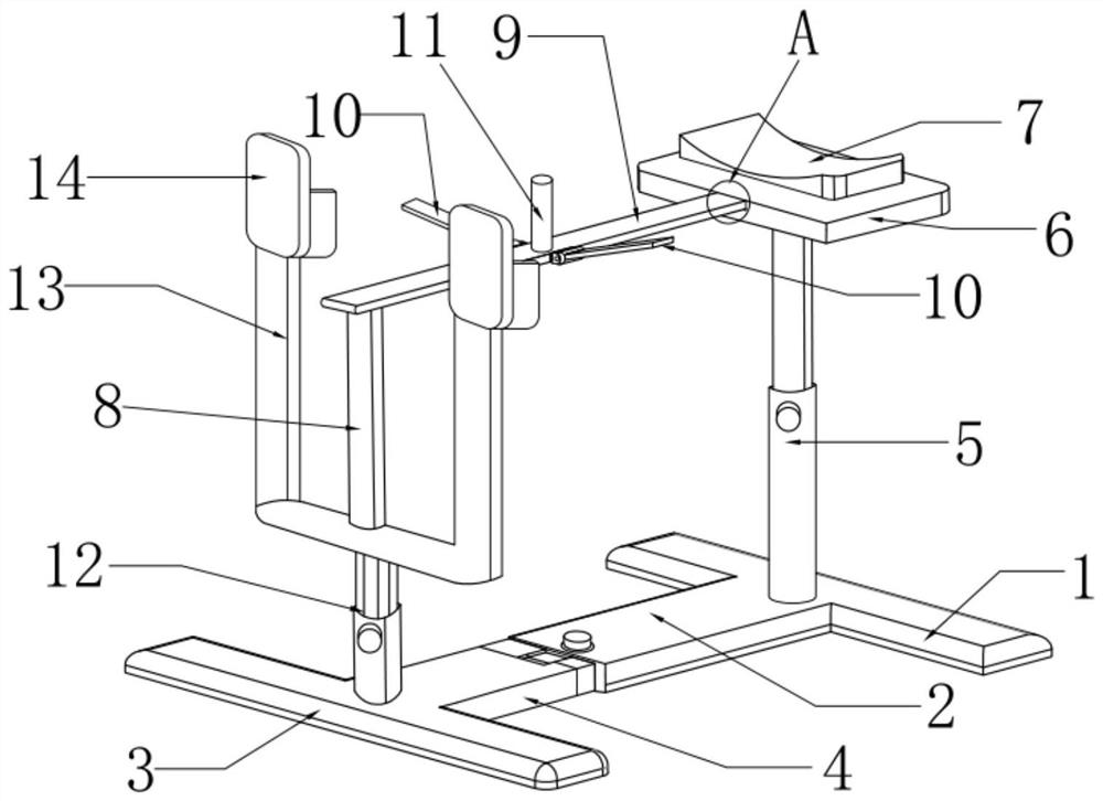
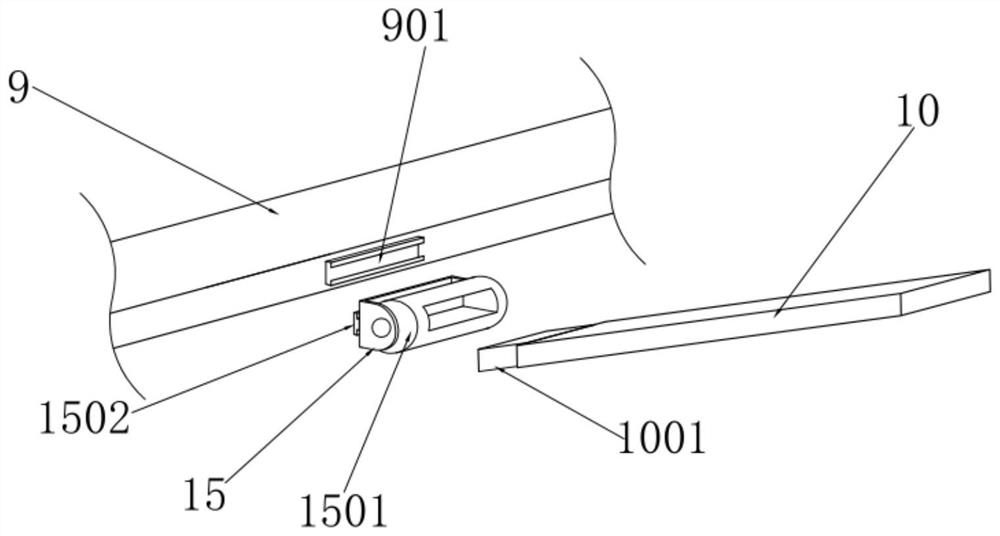
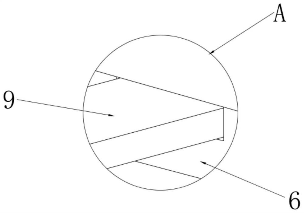
[0030] refer to Figure 1 to Figure 3 As shown, a plaster reduction support device for dislocation of the hip joint, including a rear base rail 1, a first connecting rail 2, a front base rail 3, a second connecting rail 4, a head support vertical rod 5, and a head support plate 6 , head cushion 7, upper body support vertical bar 8, upper body support plate 9, crotch baffle plate 10, retaining bollard 11, telescopic vertical bar 12, foot support U-shaped frame 13, foot pedal 14, damping rotating shaft 15;

[0031] The middle part of the inner side of the rear base crosspiece 1 is connected with the first connecting bracket 2; the inner middle part of the front base crosspiece 3 is connected with the second connecting bracket 4; the second connecting bracket 4 is movably connected in the first connecting bracket 2; The middle part of the upper surface of the base crosspiece 1 is vertically connected to the bottom of the head support vertical bar 5, the top of the head support verti

Embodiment 2

[0039] On the basis of Embodiment 1, the upper body support vertical bar and the head support vertical bar can also be designed as a telescopic structure, so that the height of the upper body support bar and the head support plate can be adjusted, thereby adjusting the height of the entire device to the doctor Convenient location.

Embodiment 3

[0041]On the basis of Embodiment 1, the width of the upper body support plate can be designed to be 30mm; the width of the head support plate 6 and the head cushion 7 is designed to be wider, which can support the shoulders;

[0042] To sum up, 1. The upper body of the child can be supported by the design of the head support and the steel bar. The design of the crotch baffle can block and protect the crotch of the child. The feet are placed on the foot pedal Above all, it can keep the child's body in a stable state, and in this stable state, plaster immobilization can be performed, which saves time and reduces the labor intensity of doctors, so that the plaster immobilization can maintain a stable state after reset.

[0043] 2. In the present invention, the second connecting gear connecting the foot pedal and the foot support U-shaped frame can move within the first connecting gear, thereby adjusting the distance between the foot pedal and the upper body support board, and can ada


PUM


Abstract

The invention discloses a hip joint dislocation gypsum reduction supporting device, which comprises a rear base crosspiece, a first connecting piece, a front base crosspiece, a second connecting piece, a head supporting vertical rod, a head supporting plate, a head cushion, an upper body supporting vertical rod, an upper body supporting plate, a crotch baffle, a blocking and protecting column, a telescopic vertical rod, a foot supporting U-shaped frame, a foot pedal and a damping rotating shaft. By means of the device, the body of a child patient can be in a stable state, gypsum fixation can be conducted in the stable state, time is saved, the labor intensity of doctors is relieved, and the stable state after restoration can be kept after gypsum fixation; and the device can adapt to child patients with different heights.

Description


Claims


Application Information

Patent Timeline
Owner 昆明市儿童医院
Why Eureka
Try Eureka