On-Camera Flashlight

Active Publication Date: 2016-07-14
YUEQING ORIGINALITY PHOTOGRAHY EQUIP
View PDF9 Cites 0 Cited by
  • Summary
  • Abstract
  • Description
  • Claims
  • Application Information

AI Technical Summary

Benefits of technology

[0005]The present invention aims to provide an on-camera flashlight whose design in structure may effectively provide a w

Problems solved by technology

The currently available flashlights in the art are attributed with having the following problems: the majority of on-camera flashlights and LED (light emitting diode) light source currently in the market are generally two separate lighting devices, while in use, the light emitting diode is often used as a device to fill light during photographing; the flashlight and the light emitting diode for fill light are separately mounted, which not only require more space to mount the devices but also require more apparatus for connection and cooperation of the parts.
Therefore, such multiple separate lighting devic

Method used


Image

  • On-Camera Flashlight
  • On-Camera Flashlight

Examples


Embodiment Construction

[0020]Embodiments of the present invention discloses an on-camera flashlight to solve the issue concerning light emitting diode light source of the on-camera flashlight that conventionally cannot provide light in multiple directions.

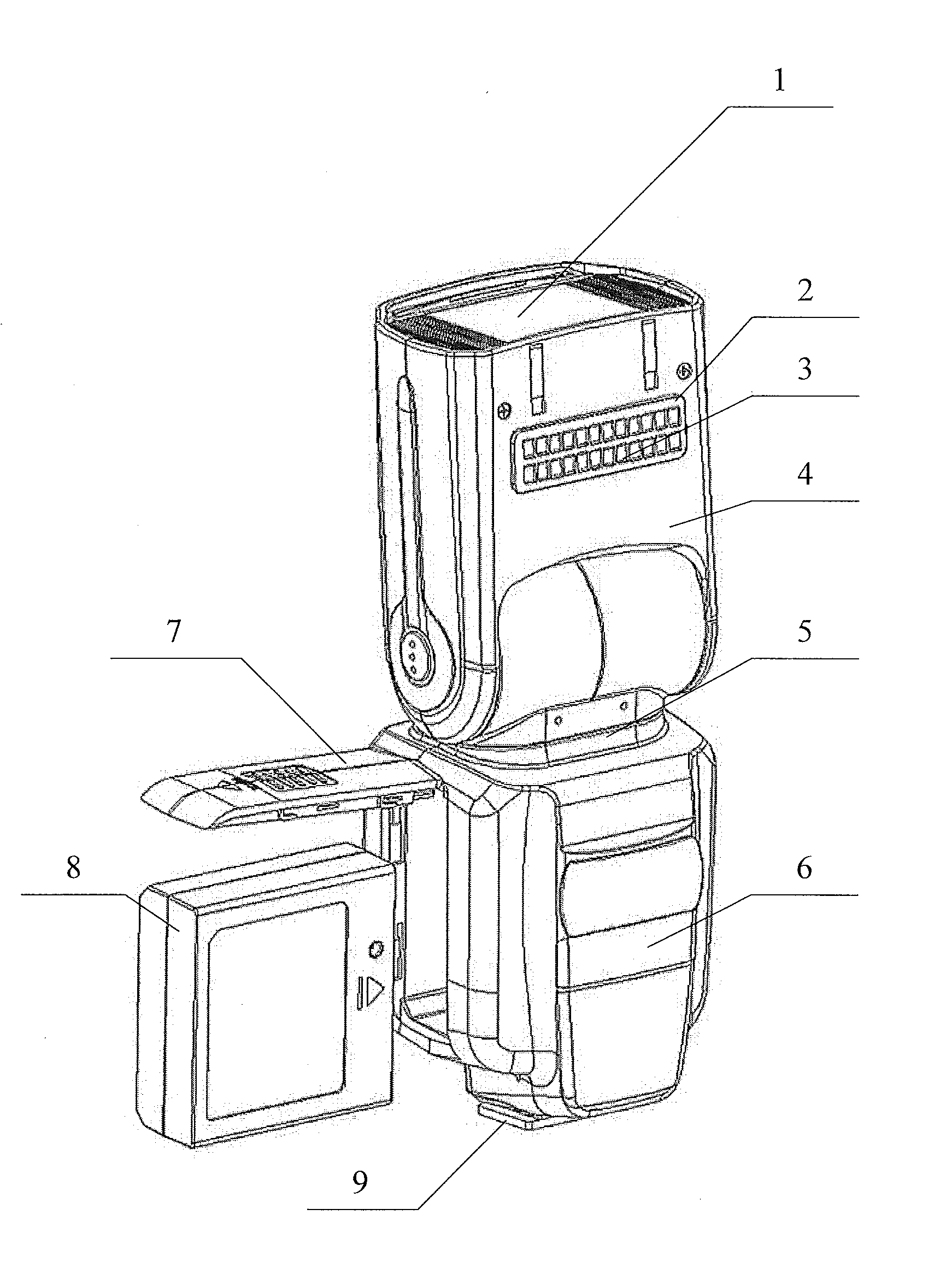
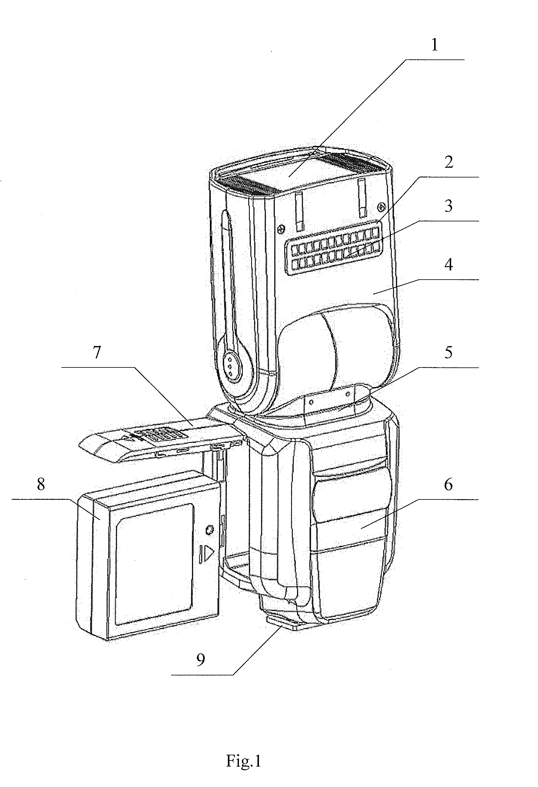
[0021]Hereinafter, technical solution in embodiments of the present invention is fully described, taken in conjunction with a drawing of an embodiment of the present invention. The embodiments illustrated below are not meant to limit the scope of the invention as defined in the Claims. FIG. 1 is a structural schematic of the on-camera flashlight provided in embodiments of the present invention, with the baffle open and the battery holder being taken out.

[0022]The on-camera flashlight provided in the present invention includes a lower light holder 6 and a top light holder 4 freely rotatably connected to the lower light holder 6. A flashlight light source 1 is mounted on the top of the top light holder 4. On the side where the top light holder 4 is mounted fa


PUM


Abstract

The present invention is an on-camera flashlight, comprising a lower light holder and a top light holder freely rotatably connected to the lower light holder. A flashlight light source is mounted on the top of the top light holder. The light emitting diode and the flashlight light source are mounted on the on-camera flashlight, combined for ease of use. Two functions-in-one lighting device saves space, avoids overloading the camera, and makes it portable. Because the two light sources are set in combination, the cooperation and sequence of the two light sources are easier to control. As the light emitting diode is mounted on the top light holder which may freely rotate with respect to the lower light holder, the light emitting diode may also freely rotate. It is also convenient to adjust the light direction. Above features all remarkably facilitate operation and versatility of the on-camera flashlight.

Description


Claims


Application Information

Patent Timeline
Owner YUEQING ORIGINALITY PHOTOGRAHY EQUIP
Why Eureka
Try Eureka