Electromechanical assembly controlled by sensed voltage

a technology of electrical components and sensed voltage, which is applied in the direction of electronic commutator control, electronic commutator with armature, electronic commutator motor control, etc., can solve the problems of negative affecting the operational availability of computing resources for customers, and injury to the operator when the air-moving assembly is removed

Active Publication Date: 2016-10-13
IBM CORP
View PDF3 Cites 0 Cited by
  • Summary
  • Abstract
  • Description
  • Claims
  • Application Information

AI Technical Summary

Benefits of technology

This patent describes a way to improve upon existing methods for monitoring voltages in electric machines used in systems like motors. It involves adding an electro-mechanical assembly that can detect changes in voltage levels caused by the machine's operation. When this happens, it moves the movable part towards its quiescent position.

Problems solved by technology

The technical problem addressed by this patent is how to provide continuously cooling to electronic devices in servers without causing damage from accidentally removing them when they shouldn't.

Method used


Image

  • Electromechanical assembly controlled by sensed voltage
  • Electromechanical assembly controlled by sensed voltage
  • Electromechanical assembly controlled by sensed voltage

Examples


Embodiment Construction

[0029]Reference is made below to the drawings, where the same reference numbers used throughout different figures designate the same or similar components.

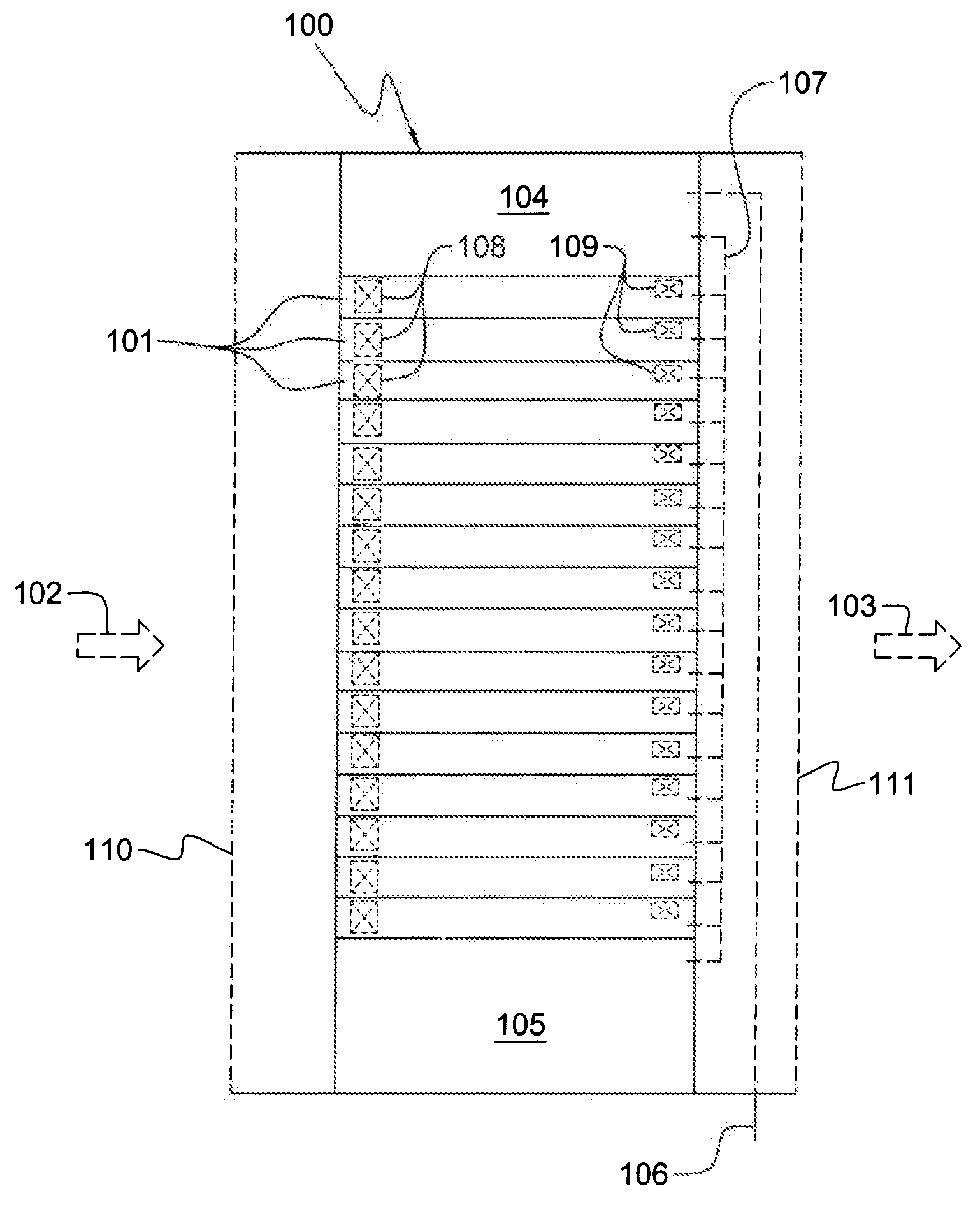
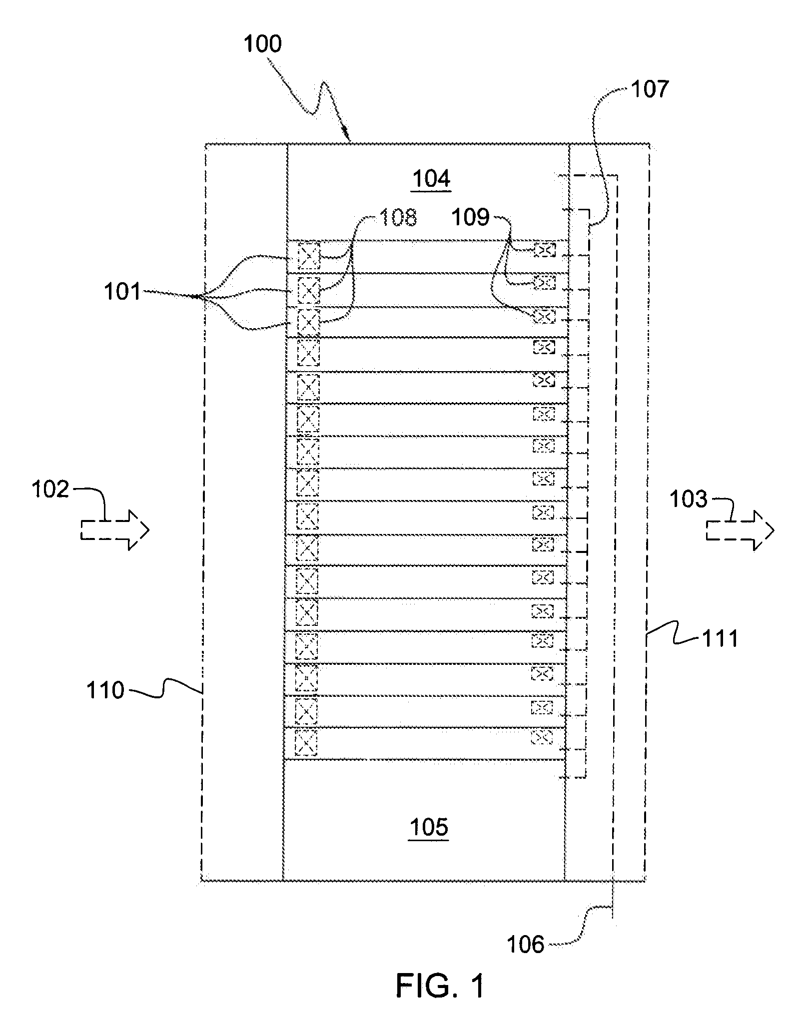
[0030]FIG. 1 depicts (by way of example) one embodiment of an electronics rack 100 with a plurality of electronic subsystems or drawers 101 to be cooled. In the embodiment illustrated, electronic systems, subsystems 101 are air-cooled by cool airflow 102 ingressing via an air inlet 110, and exhausting out an air outlet 111 as hot airflow 103. One or more air-moving assemblies 108 may be provided at the air inlet sides of electronic subsystems 101 and / or one or more air-moving assemblies 109 may be provided at the air outlet sides of electronic subsystems 101 to facilitate airflow through the individual subsystems 101 as part of the cooling apparatus of electronics rack 100. By way of example, air-moving assemblies 108 at the air inlets to electronic subsystems 101 may be or include axial fan assemblies, and air-moving assemblies 10


PUM


Abstract

An electromechanical assembly is provided controlled by voltage across a motor or with an electronic system. The electromechanical assembly includes a control circuit coupled to sense voltage at the motor or within the electronic system, and an electromechanical actuator energized by the voltage sensed by the control circuit. A movable element is movable by the electromechanical actuator from an operational position to a quiesced position when the voltage sensed by the control circuit falls below a quiesced threshold. In certain embodiments, the voltage being sensed is across a motor of an air-moving assembly, which resides within a support structure, or the voltage being sensed is within the electronic system, which resides within the support structure, and the movable element is an interlock element which interlocks to the support structure to prevent removal of one or more components from the structure when sensed voltage is above the quiesced threshold.

Description


Claims


Application Information

Patent Timeline
Owner IBM CORP
Why Eureka
Try Eureka