Telescopic limiting structure, camera body and camera

a limiting structure and telescopic technology, applied in the field of telescopic limiting structure, can solve the problems of inconvenient detachment of lenses, inconvenient use, and inconvenience for users, and achieve the effects of convenient and steady pressing, avoiding interference of operations, and smooth us

Active Publication Date: 2017-08-03
SZ DJI TECH CO LTD
View PDF7 Cites 13 Cited by
  • Summary
  • Abstract
  • Description
  • Claims
  • Application Information

AI Technical Summary

Benefits of technology

This patented technology allows for two directions within an optical system that allow it to extend or contract without affecting its orientation during use. It also prevents rotation and deviation between different parts inside the device's housing due to gravity forces caused by holding them with both hands at once. Additionally, this design makes it easy to attach and remove any part used on top because there are no obstacles like fingers pressing against the lenses themselves.

Problems solved by technology

This patented technical issue addressed by this patents relates to improving the accuracy and stability of an optical device used with cameras such as monoculars or binocular systems. Traditional methods involve attaching a separate member called a zoom barrel onto the assembly's rings before inserting them inside a lensesheater slot. However, these techniques may cause damage if they shouldn’t work properly during usage.

Method used


Image

  • Telescopic limiting structure, camera body and camera
  • Telescopic limiting structure, camera body and camera
  • Telescopic limiting structure, camera body and camera

Examples


Embodiment Construction

[0033]The technical solutions in the embodiments of the present disclosure are hereinafter described with reference to the accompanying drawings. The described embodiments are only some rather than all of the embodiments of the present disclosure. All other embodiments obtained by a person of ordinary skill in the art based on the embodiments of the present disclosure without creative efforts shall fall within the scope of protection of the present disclosure.

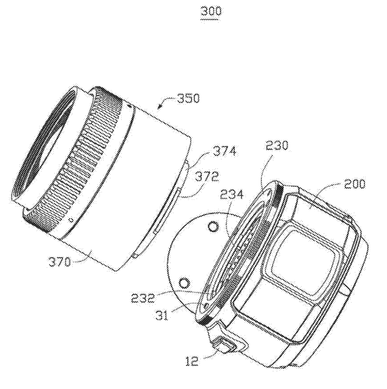
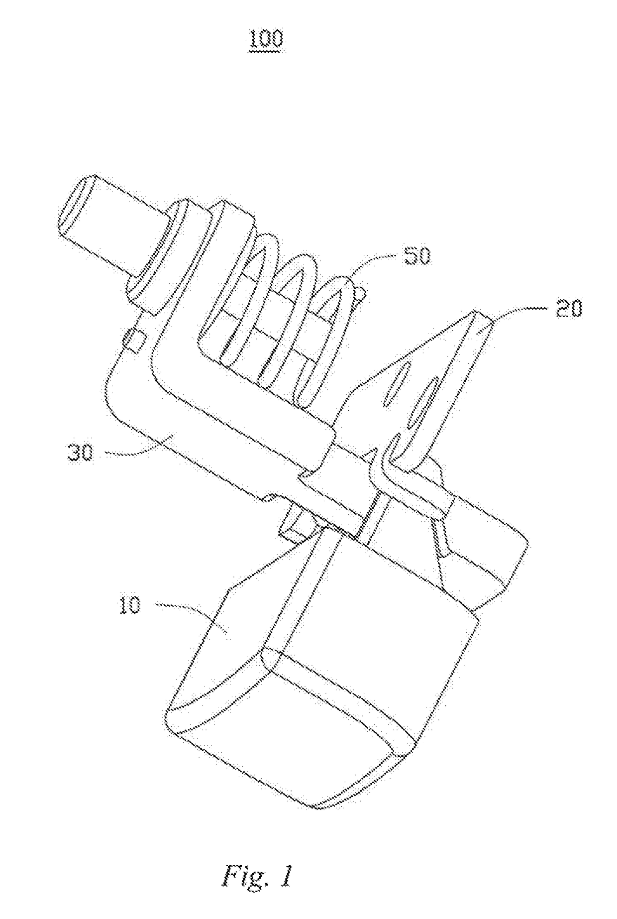
[0034]A telescopic limiting structure provided in the embodiments of the present disclosure can be mounted into an object and fitted with another object, so as to prevent the rotation and detaching of the another object. The objects can be but are not limited to the camera body and the lens of a camera. For example, the telescopic limiting structure can he used for mounting into the camera body and fitting with the lens, which can prevent the lens from rotating and eventually falling off and can facilitate detachment and attachmen


PUM


Abstract

A telescopic limiting structure includes a first retractable member, including a first inclined face and a second retractable member including a second inclined face bearing against the first inclined face. The first retractable member is configured to move along a first direction. The first inclined face and the second inclined face are configured to drive the second retractable member to move along a second direction in response to the first retractable member moving along the first direction. The second direction is different from the first direction.

Description


Claims


Application Information

Patent Timeline
Owner SZ DJI TECH CO LTD
Why Eureka
Try Eureka