Scintillator panel and radiation detector
- Summary
- Abstract
- Description
- Claims
- Application Information
AI Technical Summary
Benefits of technology
Problems solved by technology
Method used
Image

Examples
example 1
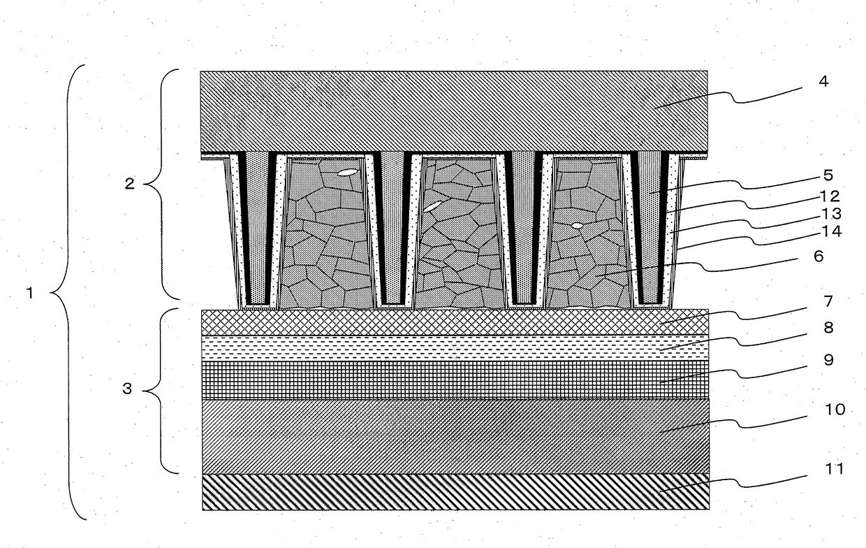
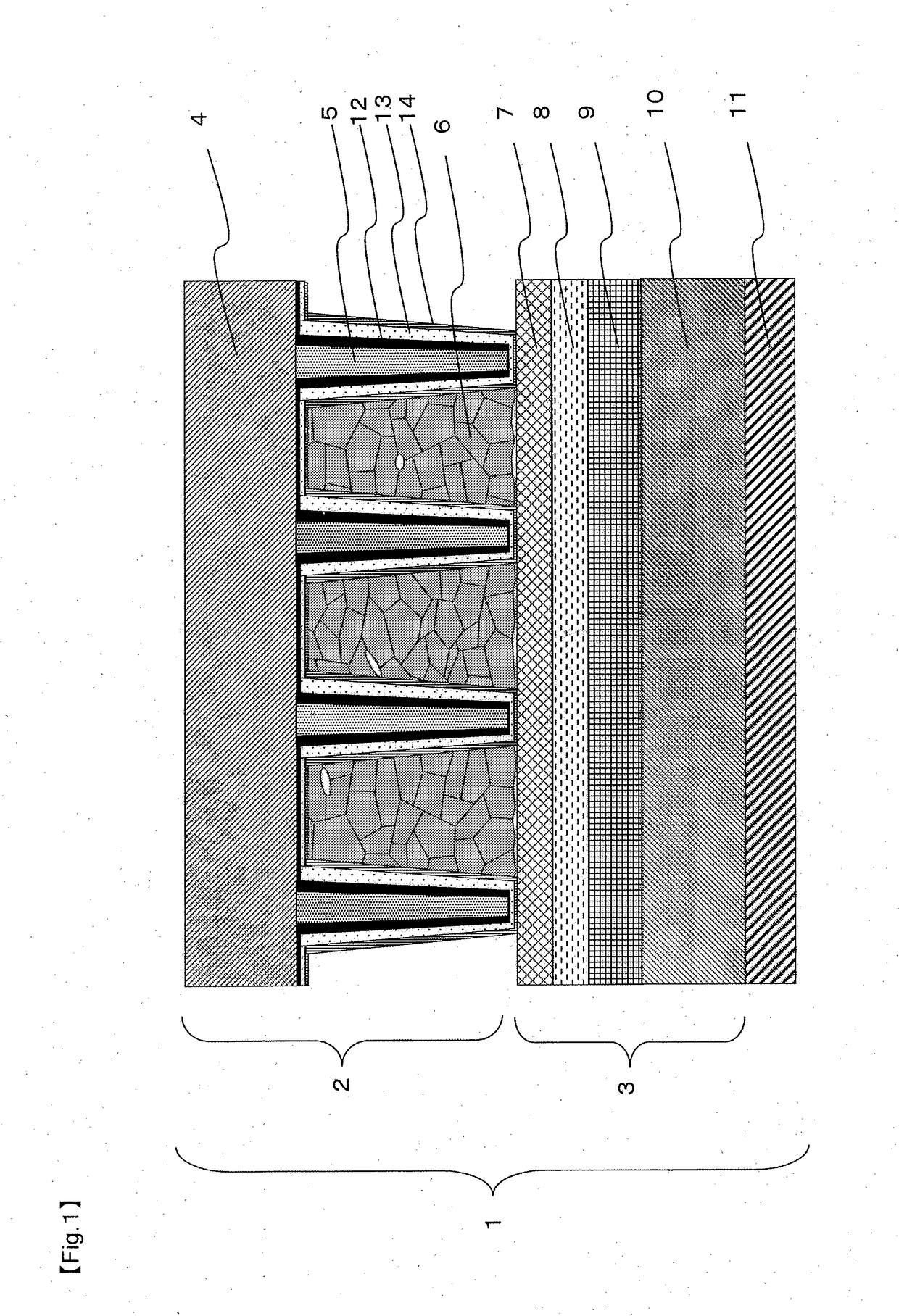
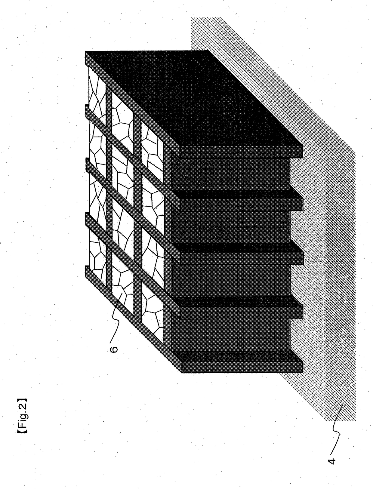
[0150]0.11 g / cm2 of a CsI:Tl powder was supplied onto a base material provided with grid-like barrier ribs, and was flattened by a squeegee, and put in a Nylon (registered trademark) bag together with the base material, and the opening of the bag was thermally welded to seal the bag. The bag was set in an isostatic pressure press apparatus (manufactured by Kobe Steel, Ltd.), and the powder was press-packed at a pressure of 400 MPa and a temperature of 25° C. to prepare a scintillator panel 1.
[0151]The CsI:TI packed in cells had a grain boundary. The CsI:TI packed in the cells had a porosity of 5% and an average particle size of 25 μm.
[0152]The prepared scintillator panel 1 was set in a FPD (PaxScan3030; manufactured by Varian Company) to prepare a radiation detector. The radiation detector was irradiated with an X-ray with a tube voltage of 60 kVp from the substrate side of the scintillator panel 1, and the amount of light emitted from a scintillator layer was detected by the FPD to
example 2
[0153]Except that in press-packing, the pressure was 60 MPa, and the temperature was 150° C., the same procedure as in Example 1 was carried out to prepare a scintillator panel, and evaluation was performed. The phosphor packed in cells of the obtained scintillator panel 2 had a grain boundary, and had a porosity of 2% and an average particle size of 35 μm. The luminance of the scintillator panel 2 was 110 in terms of a relative value where the luminance of the scintillator panel 1 is 100. Thus, the scintillator panel 2 exhibited a good luminance. The scintillator panel 2 also exhibited a good image sharpness.
example 3
[0154]The reflecting layer paste was applied to a surface of a base material provided with grid-like barrier ribs, and was left standing for 5 minutes, and the deposited reflecting layer paste was then scraped off by a rubber squeegee with a hardness of 80°. Thereafter, drying was performed in hot air ovens at 80° C.° and 130° C. for 30 minutes each to form a reflecting layer on the surface of the barrier rib and on portions where the barrier rib was not formed. Thereafter, in the same manner as in Example 1, a CsI:Tl powder was supplied, and press-packed to prepare a scintillator panel 3, and evaluation was performed.
[0155]The phosphor packed in cells of the obtained scintillator panel 3 had a grain boundary, and had a porosity of 5% and an average particle size of 25 μm. The luminance of the scintillator panel 2 was 130 in terms of a relative value where the luminance of the scintillator panel 1 is 100. Thus, the scintillator panel 2 exhibited a good luminance. The scintillator panel
PUM
 Abstract
Description
Claims
Application Information
 - R&D Engineer
- R&D Manager
- IP Professional
- Industry Leading Data Capabilities
- Powerful AI technology
- Patent DNA Extraction
Browse by: Latest US Patents, China's latest patents, Technical Efficacy Thesaurus, Application Domain, Technology Topic.
© 2024 PatSnap. All rights reserved.Legal|Privacy policy|Modern Slavery Act Transparency Statement|Sitemap