Light Assembly and Alignment Device

a technology of alignment device and assembly, which is applied in the direction of lighting device details, lighting support devices, lighting and heating apparatus, etc., can solve the problems of difficult to find blind holes and problematic installation of fixtures, and achieve quick and accurate assembly installation, selective raising and lowering, and increased heat removal

Active Publication Date: 2018-05-03
SCHNEIDER ANDREW MICHAEL
View PDF18 Cites 14 Cited by
  • Summary
  • Abstract
  • Description
  • Claims
  • Application Information

AI Technical Summary

Benefits of technology

This patent describes a system that allows for quick installation of electronic devices (such as lights) without damaging their wires. It includes a guide that helps the installer insert the device correctly into the brackets attached to the ceiling. There are also other components like a spacer and a cover to keep the equipment away from the ceiling while being hidden during installation. Additionally, there may have a latch mechanism to help prevent accidental movement of the light's cables. Overall, these technical improvements improve the efficiency and effectiveness of installing electronic devices.

Problems solved by technology

This patent describes a technical problem with current methods used in suspending lights on buildings. These methods require holes through brackets and are difficult to install without looking at them. There is also a challenge when attaching heavy objects such as lamps to this method due to the lack of visibility during the process.

Method used


Image

  • Light Assembly and Alignment Device
  • Light Assembly and Alignment Device
  • Light Assembly and Alignment Device

Examples


Embodiment Construction

[0041]While the invention will be described in connection with one or more preferred embodiments, it will be understood that it is not intended to limit the invention to those embodiments. On the contrary, it is intended to cover all alternatives, modifications and equivalents as may be included within the spirit and scope of the invention as defined by the appended claims.

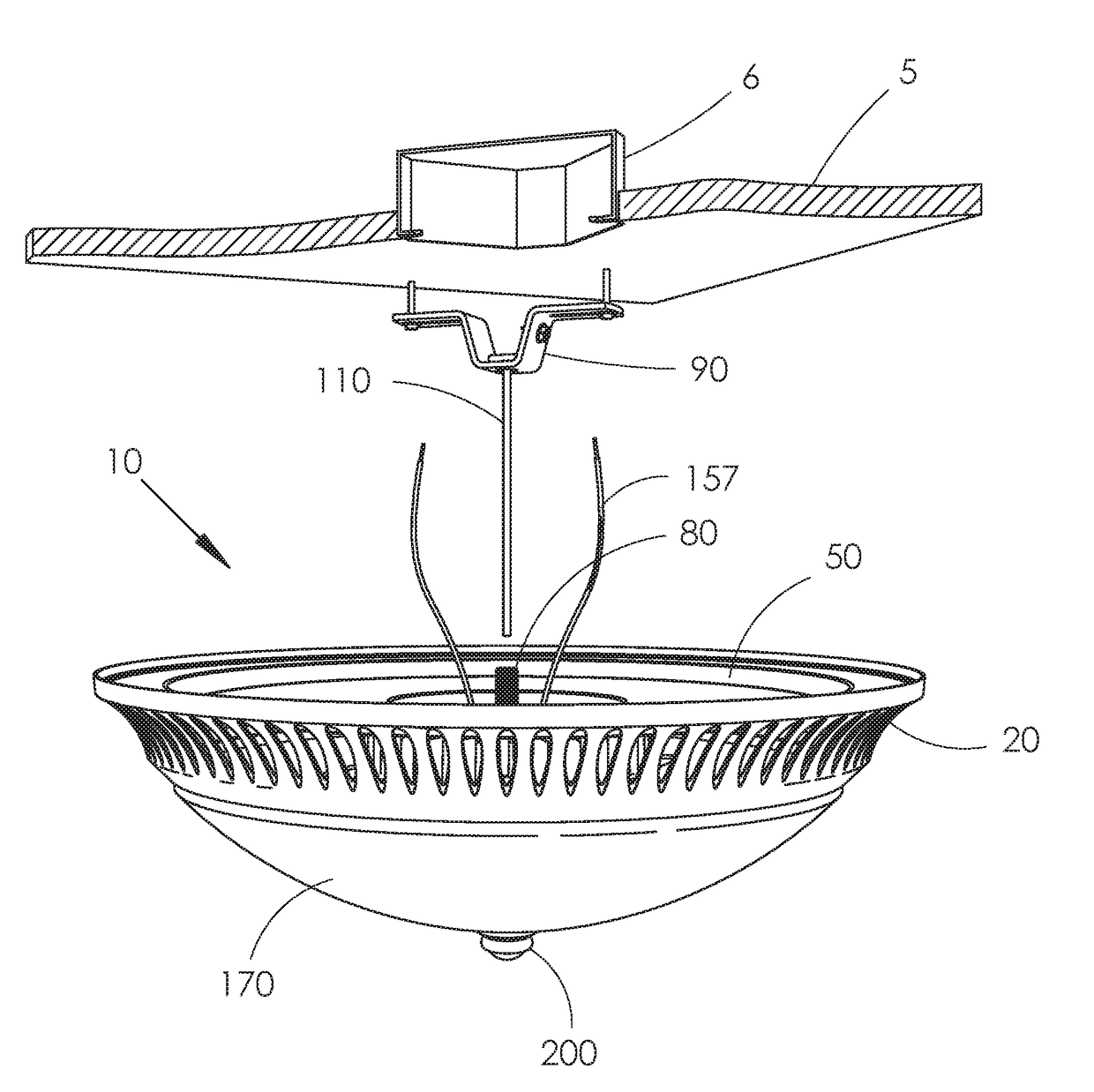
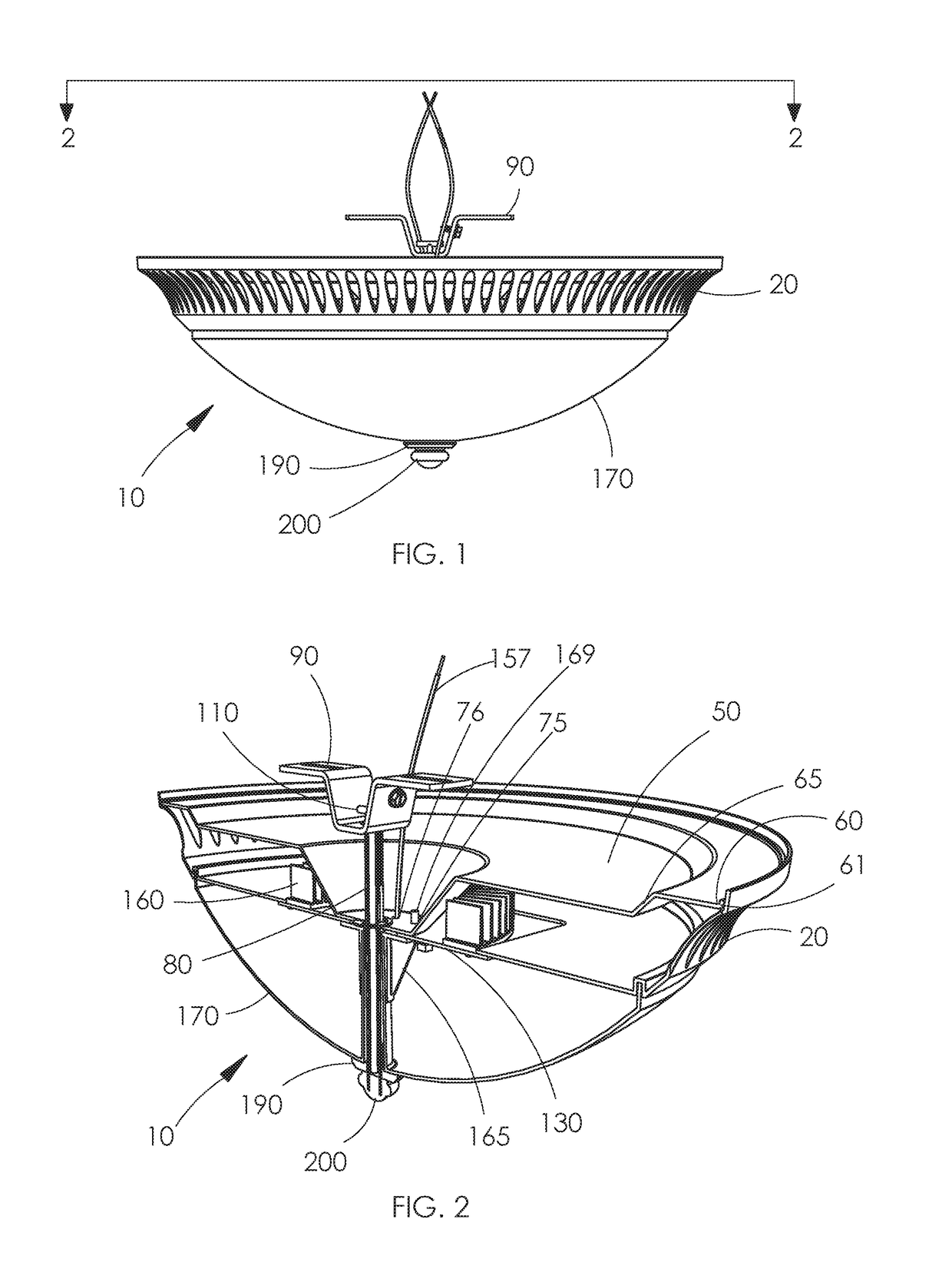
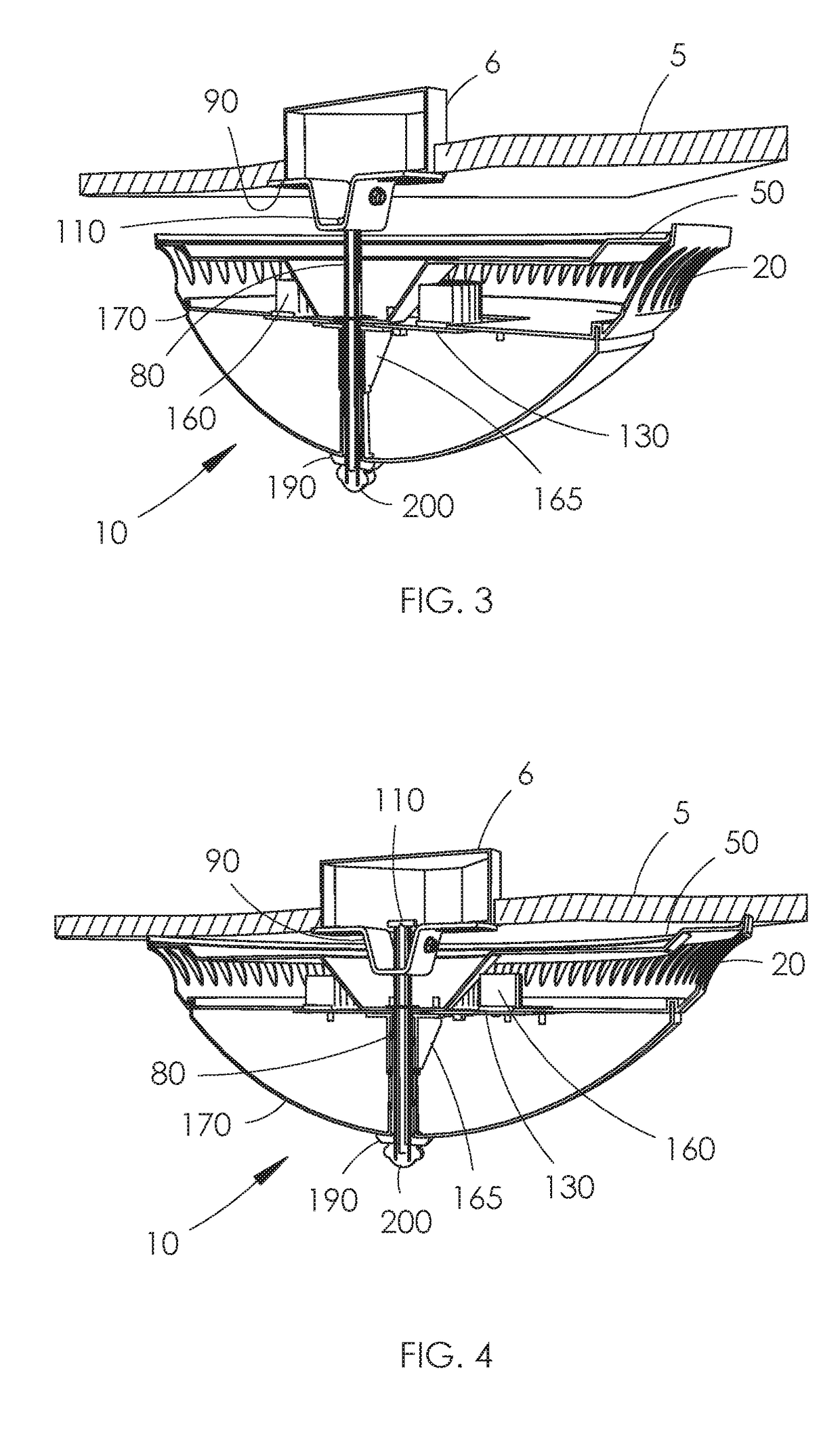
[0042]Turning now to FIGS. 1-6, it is seen that a preferred embodiment of the present invention is illustrated. A light assembly 10, or simply assembly or fixture, is shown in relation to a ceiling 5 adjacent the recessed electrical box 6. The assembly 10 has a spacer 20, a lid 50, a rod 80 a bracket 90, a guide 110, electronics 130, a heat sink 160, a lifter 165, a cover 170, a washer 190 and a nut 200. Each of these components are described in detail below. It is appreciated that these components are not all required components for each inventive aspect of the present invention.

[0043]The spacer 20 is best seen in F


PUM


Abstract

The present invention relates to an improved light assembly and alignment device. One embodiment of the assembly can have a spacer, a lid, a rod, a bracket, a guide, electronics, a cover and a nut. The spacer has a perimeter sidewall that is vented. A guide having a keeper and a body can be passed through a hole in the bracket. The rod can receive the body of the guide wherein the rod is aligned with the hole in the bracket. A nut at an end of the rod supports the cover by preventing it from sliding off from the end of the rod. The nut also is used to turn the rod so that it advances through the bracket hole to raise the assembly to the ceiling. Another embodiment has a square nut that is seated in a bracket when the rod is passed through a bracket slot.

Description


Claims


Application Information

Patent Timeline
Owner SCHNEIDER ANDREW MICHAEL
Why Eureka
Try Eureka