Twist drill with unequal flute spacing and unequal relief angles

a drill bit and flute technology, applied in the field of rotary cutting tools, can solve the problems of rotating drill bit vibrations that cause “chatter” recur periodically, more complex geometrical design, and more difficult manufacturing of twist drill bits

Active Publication Date: 2018-09-06
KENNAMETAL INC
View PDF1 Cites 4 Cited by
  • Summary
  • Abstract
  • Description
  • Claims
  • Application Information

AI Technical Summary

Benefits of technology

The technical effect of this patented technology is that it provides an understanding for how well things work with each other.

Problems solved by technology

The technical problem addressed in this patent is how to improve the performance and durability of drill bits made of cemented carbide materials while maintaining their ability to cut efficiently during drilling processes without causing damage to the surrounding parts like the drill itself.

Method used


Image

  • Twist drill with unequal flute spacing and unequal relief angles
  • Twist drill with unequal flute spacing and unequal relief angles
  • Twist drill with unequal flute spacing and unequal relief angles

Examples


Embodiment Construction

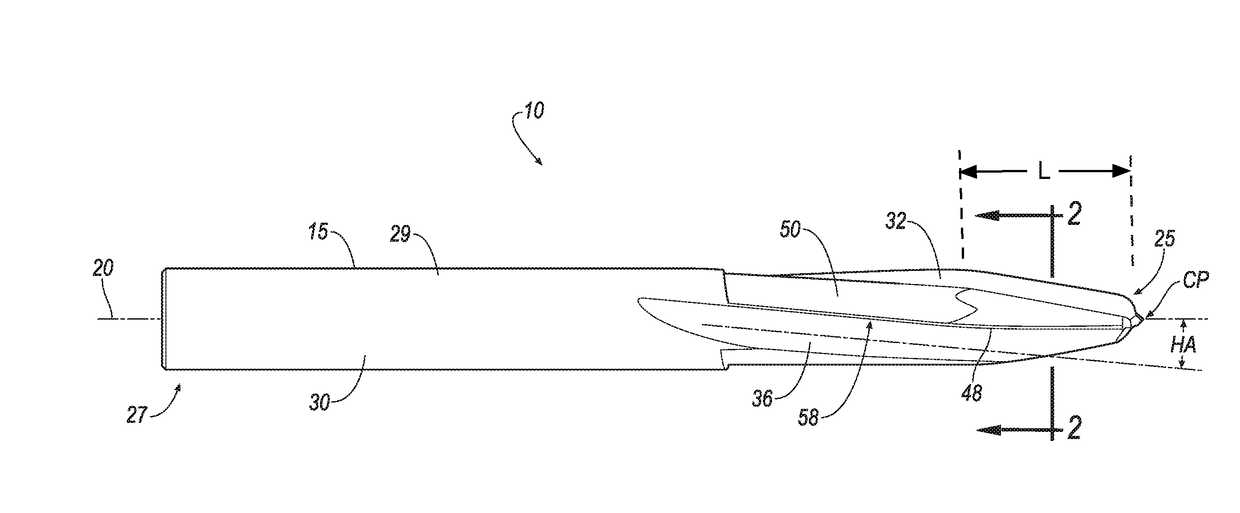
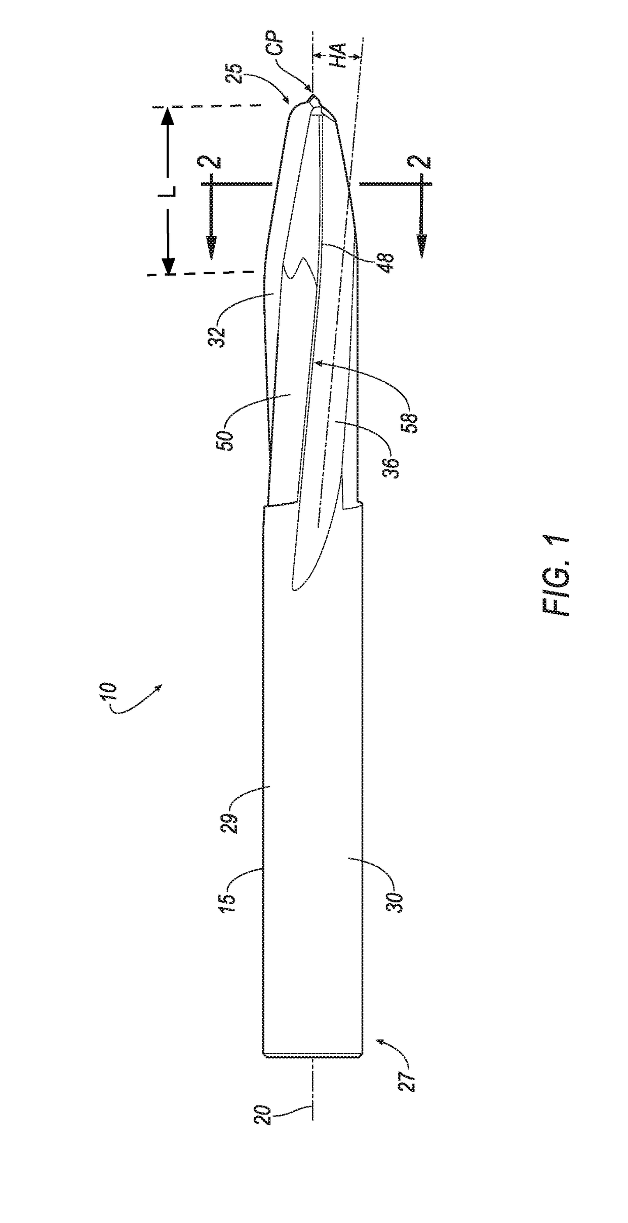
[0020]In one aspect of the invention, the invention is directed to a rotary cutting tool having at least one helical flute. For purposes of explanation, a twist drill will be described herein with the understanding that the invention is applicable to other cutting tools having one or more helical flutes, such as, for example, taps and reamers. In addition, a cutting tool having three helical flutes is described herein. However, it will be appreciated that the invention is not limited by the number of helical flutes, and that the invention can be practiced with a cutting tool having two or more helical flutes.

[0021]Referring to FIGS. 1 and 2, there is shown a cutting tool 10 which, for purposes of description herein, will be referred to as a monolithic twist drill, having a shaft 15 with a longitudinal axis 20. “Monolithic”, as used herein, does not mean that the rotary cutting tool must be made from a single material. The rotary cutting tool may indeed be fabricated from a combination


PUM

PropertyMeasurementUnit
Angleaaaaaaaaaa
Angleaaaaaaaaaa
Angleaaaaaaaaaa

Abstract

A twist drill having a shaft with a longitudinal axis, wherein the cutting tool includes a plurality of flutes extending about the longitudinal shaft along a helix angle and a plurality of lands adjacent the flutes. Each land has a cutting edge adjacent a corresponding flute and a margin (i.e. relief surface). A cutting point is adjacent a forward end of the shaft. A first, second and third forward cutting surfaces are adjacent the first, second and third cutting edges, respectively, and extend proximate the cutting point axially rearward for a predetermined length about the longitudinal axis of the shaft. The cutting edges are unequally angularly spaced from each other, and each forward cutting surface has a primary relief angle that are unequal to each other.

Description


Claims


Application Information

Patent Timeline
Owner KENNAMETAL INC
Why Eureka
Try Eureka