Infrared target source positioning tracking calibration method

A calibration method and infrared target technology, which is applied in the optical field to achieve accurate positioning and tracking of infrared target sources

Inactive Publication Date: 2016-05-04
SHANGHAI PRECISION METROLOGY & TEST RES INST
View PDF9 Cites 2 Cited by
  • Summary
  • Abstract
  • Description
  • Claims
  • Application Information

AI Technical Summary

Benefits of technology

This technology allows for precise location and trackability on an object's surface through its own unique characteristics that are caused when it emits light waves or scans across different angles at once.

Problems solved by technology

The technical problem addressed by this patented system is how accurately locate and track an object that emits light when it moves around within space without any obstacles or other objects between them (known as 3D). This requires precise measurements from multiple cameras at different angles while also ensuring stable operation over time for reliable results.

Method used


Image

  • Infrared target source positioning tracking calibration method

Examples


Embodiment Construction

[0011] A method for positioning, tracking and calibrating an infrared target source proposed by the present invention will be described in further detail below in conjunction with the accompanying drawings and specific embodiments. Advantages and features of the present invention will be apparent from the following description and claims. It should be noted that the drawings are all in very simplified form and use imprecise ratios, which are only used to facilitate and clearly assist the purpose of illustrating the embodiments of the present invention.

[0012] The core idea of ​​the present invention is that the infrared target source positioning and tracking calibration method provided by the present invention realizes the expansion from plane angle offset to three-dimensional space angle offset, so that the infrared target source positioning and tracking is more accurate.

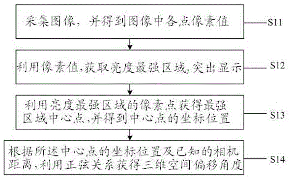
[0013] figure 1 It is a schematic flowchart of the steps of the infrared target source positioning trac


PUM


Abstract

The invention provides an infrared target source positioning tracking calibration method, and the method comprises the steps: collecting an image, and obtaining the pixel values of all points in the image; obtaining a region with the highest brightness through the pixel values, and highlighting the region; obtaining the central point of the region with the highest brightness through the pixels of the region with the highest brightness, and obtaining the coordinates of the central point; and obtaining a three-dimensional space deviation angle according to the coordinates of the central point and a known camera distance through a sine relation. The method achieves the extension of plane angle deviation to three-dimensional spatial angle deviation, thereby enabling the infrared target source positioning tracking to be more accurate.

Description


Claims


Application Information

Patent Timeline
Owner SHANGHAI PRECISION METROLOGY & TEST RES INST
Why Eureka
Try Eureka