Photoelectric support frame system for automatic conveying

A technology of support system and conveying system, which is applied in the field of conveying support, can solve the problems of inability to realize free adjustment of detection points, low work efficiency, cumbersome operation process, etc., and achieve the effect of convenient daily inspection, convenient maintenance and convenient use

Pending Publication Date: 2019-01-22
SHANGHAI JIAZHENG MACHINERY
View PDF0 Cites 0 Cited by
  • Summary
  • Abstract
  • Description
  • Claims
  • Application Information

AI Technical Summary

Benefits of technology

This new technology allows for better utilization of lightweight materials while maintaining their strengths over time without requiring expensive equipment or complicated processes like weldings. It also provides an efficient way to attach detectors onto different surfaces that require precise alignment during operation. Overall, this innovative technology makes it easier and more affordable than previous methods.

Problems solved by technology

This patented technical problem addressed by this patent relates to improving braces that have multiple detect points while being easy-to-use without wasting effort on their owners during operations due to lack of flexibility. Existing brackets may require complex structures and difficult assembly processes making it hard for users who want more freedom than they could afford themselves.

Method used


Image

  • Photoelectric support frame system for automatic conveying
  • Photoelectric support frame system for automatic conveying

Examples


Embodiment

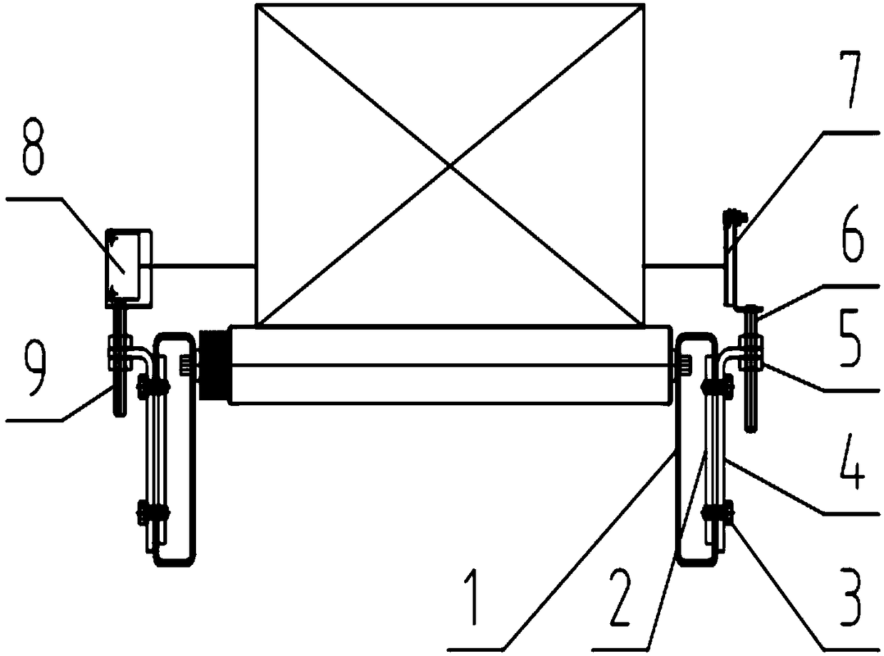
[0024] A photoelectric support system for automatic delivery, its structure is as follows Figure 1-2 As shown, it includes: a C-shaped body 1 connected to both sides of the conveying system, a splint 2 and an L-shaped splint 4 connected to the C-shaped body 1, and one or more splints can be arranged on each side of the C-shaped body , so that a greater number of other components can be connected as required. Emitting head support 9 and reflector support 6 are respectively fixed on an L-shaped splint 4 on both sides, and photoelectric emission head 8 is connected on emission head support 9, and reflector support 6 is connected with photoelectric reflector 7.


PUM


Abstract

The invention relates to a photoelectric support frame system for automatic conveying. The system comprises a C-shaped machine body connected on two sides of the conveying system, clamping plates andL-shaped clamping plates which are connected on the C-shaped machine body, emitter support frames and reflector support frames which are respectively fixed on two sides of one L-shaped clamping plate,a photoelectric emitter connected on one of the emitter support frames, and a photoelectric reflector connected on the other of the reflector support frames. Compared with the prior art, the system has the advantages of wide use range, simple structure, flexibility and changeability, stability and reliability, convenient maintenance and the like, can realize photoelectric horizontal movement, rotation angle adjustment and height adjustment, can freely change the three-dimensional space position of photoelectric detection according to needs in actual work, and can be conveniently, efficientlyand widely used in an automatic conveying system.

Description


Claims


Application Information

Patent Timeline
Owner SHANGHAI JIAZHENG MACHINERY
Why Eureka
Try Eureka