Torsion spring fixation in automatic drug delivery device

a technology of automatic delivery and twisting spring, which is applied in the direction of intravenous devices, automatic syringes, syringes, etc., can solve the problems of high production cost of poor rotational tolerance of hooked spring ends, and high cost of producing helical torsion springs with hooked ends. , to achieve the effect of reducing or eliminating at least one drawback

Inactive Publication Date: 2019-02-14
NOVO NORDISK AS
View PDF3 Cites 0 Cited by
  • Summary
  • Abstract
  • Description
  • Claims
  • Application Information

AI Technical Summary

Benefits of technology

The technical effect of this patented solution is that it eliminates certain problems with previous methods by providing a more efficient way to improve performance without compromising their quality.

Problems solved by technology

This patent describes a problem with current methods of attaching a threaded torsion spring to an injector device. These methods involve costly manufacturing processes and require precise placement of the spring ends before assembly into the device. Additionally, there can be variations in the spring's performance due to factors like temperature changes and wear caused by repeated use. Therefore, this patent proposes a new method called "cheese-effective" spiral torsion spring design that reduces these issues while still maintaining good performance.

Method used


Image

  • Torsion spring fixation in automatic drug delivery device
  • Torsion spring fixation in automatic drug delivery device

Examples


Embodiment Construction

[0050]When in the following relative expressions, such as “upper” and “lower”, are used, these refer to the appended figures and not necessarily to an actual situation of use. The shown figures are schematic representations for which reason the configuration of the different structures as well as their relative dimensions are intended to serve illustrative purposes only.

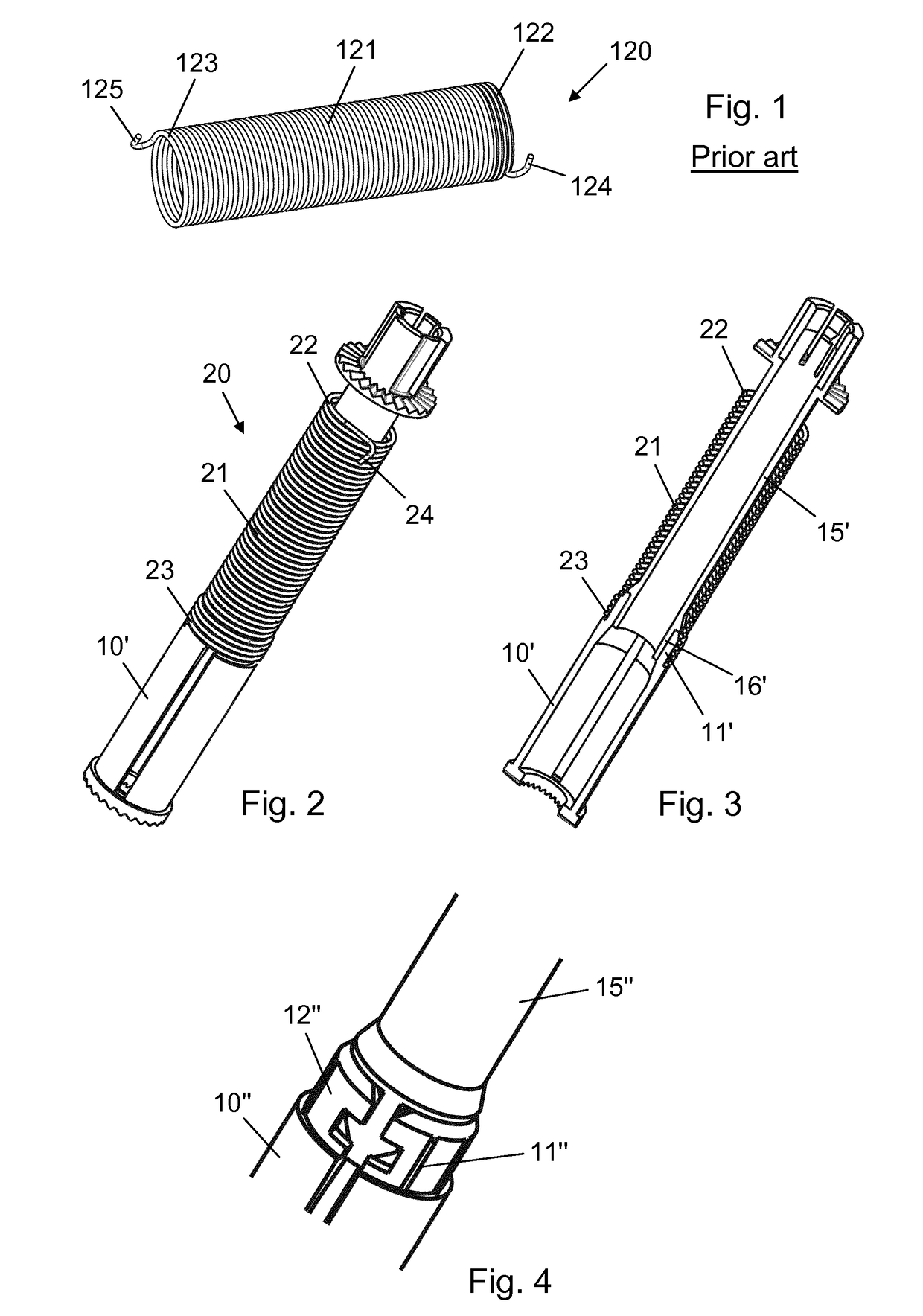
[0051]FIG. 1 shows a torsion spring 120 as conventionally used in the art of torsion spring based automatic injection devices. The torsion spring 120 comprises a helically coiled body 121 which extends longitudinally between a proximal end portion 122 and a distal end portion 123. The proximal end portion 122 terminates in a proximal (open) hook 124 while the distal end portion 123 terminates in a distal (open) hook 125. In conventional applications the proximal hook 124 is attached to a proximal receiving section which is stationary with respect to the injection device housing, and the distal hook 125 is attached to a


PUM


Abstract

A drug injection device (1) comprising a dose expelling mechanism for expelling drug from a reservoir through a reservoir outlet, the dose expelling mechanism comprising: a first component (40), a second component (10, 10′, 15′, 10″, 15″), and a torsion spring element (20) for inducing relative rotation between the first component (40) and the second component (10, 10′, 15′, 10″, 15″) to execute a dose expelling operation, the torsion spring element (20) extending along a longitudinal axis and comprising: a first spring end portion (22) being rotationally restrained with respect to the first component (40), and a second spring end portion (23) exhibiting an end portion inner diameter in a relaxed state of the torsion spring element (20), wherein the second spring end portion (23) is fitted over a spring receiving portion (11) of the second component (10, 10′, 15′, 10″, 15″), the spring receiving portion (11) having a transversal dimension which is larger than the end portion inner diameter, and the fitting of the second spring end portion (23) over the spring receiving portion (11) being configured to provide a sticking friction engagement between the two when the torsion spring element (20) is strained to exert a maximum in-use torque.

Description


Claims


Application Information

Patent Timeline
Owner NOVO NORDISK AS
Why Eureka
Try Eureka