Dual speed and position wheel transducer

a transducer and position technology, applied in the direction of instruments, aircraft braking arrangements, braking systems, etc., can solve the problems of affecting the accuracy of angular position measuremen

Active Publication Date: 2019-02-28
HYDRO AIRE AEROSPACE CORP
View PDF2 Cites 2 Cited by
  • Summary
  • Abstract
  • Description
  • Claims
  • Application Information

AI Technical Summary

Benefits of technology

This patented innovation allows for accurate measurement of angle and rotation velocities during anti-skidding braking without requiring modifications from older equipment used for piloted airplanes or military fighter jets. It also includes two different types of components: one measures only angular positions while another measure both movements simultaneously. These new technologies can be integrated within the same device called the sensor itself but they are designed specifically for these applications.

Problems solved by technology

Increasing demand from commercial aviation authorities over the use of multiple anti-skid valve controls (ASVC), including those controllable hydraulic actuators, requires accurate measurement of the rotation speeds of each wheel during different flight phases without compromising safety measures due to potential instability caused by changes in inductive coupling between the wheel and the system components. Current methods involve converting the input into digital form before processing them accurately, which limits usability even if there were no significant change in ground pressure.

Method used


Image

  • Dual speed and position wheel transducer
  • Dual speed and position wheel transducer
  • Dual speed and position wheel transducer

Examples


Embodiment Construction

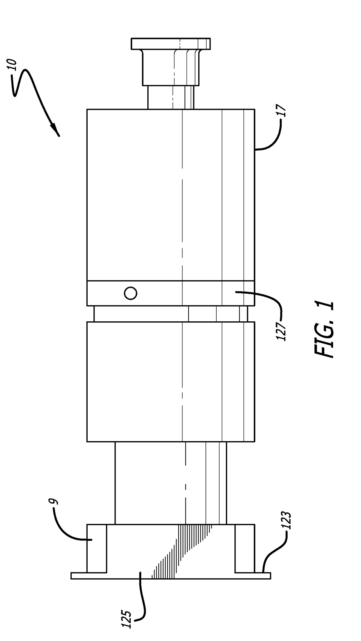
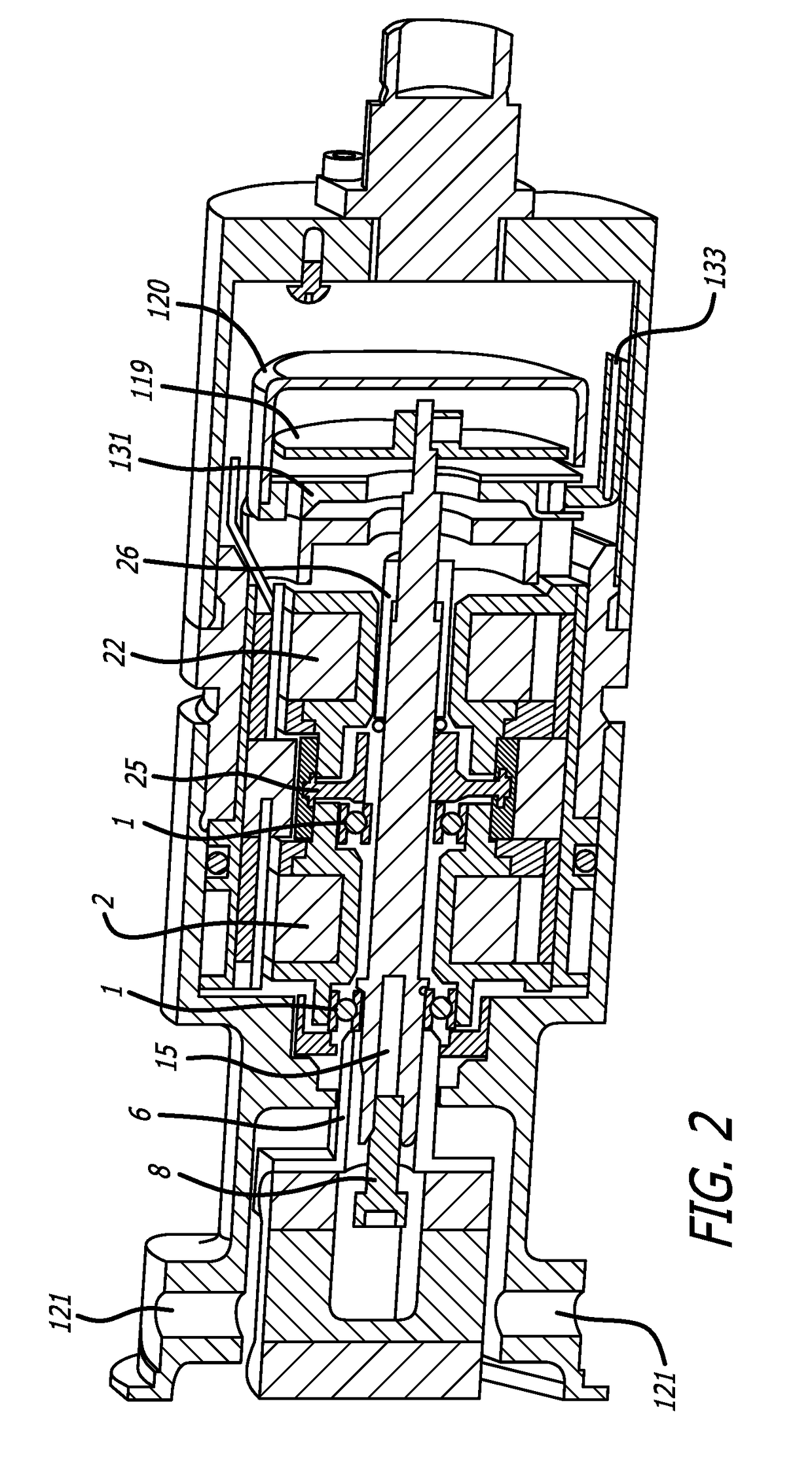
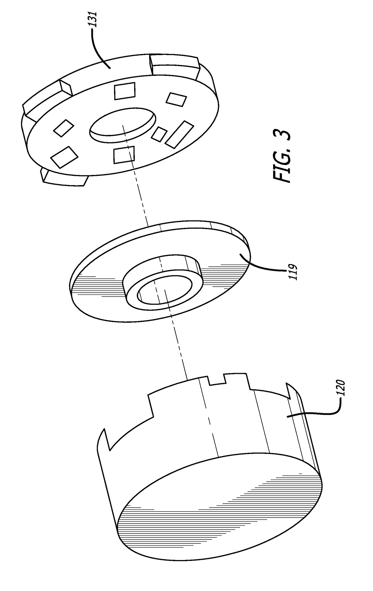
[0011]The present invention provides a wheel speed transducer that is part of an antiskid braking system for an aircraft to prevent deep skids prior to controlled deceleration. Deep skids are a particular problem for aircraft since repeated deep skids can damage tires and reduce braking efficiency. With reference to FIG. 1, the present invention is embodied in a wheel speed transducer 10 for each wheel brake of a landing gear of an aircraft, for measuring wheel speed and generating wheel speed signals that are a function of the rotational speed of the brake wheel. This embodiment of the wheel speed transducer includes a dual coil variable reluctance mechanism used for anti-skid control in combination with, and contained within the same housing as, a magnetic encoder that is used for wheel speed detection below approximately ten knots and for forward versus reverse motion detection, where the magnetic encoder can also be used to measure angular displacements of the wheel in addition to


PUM


Abstract

A wheel speed measuring device for an aircraft braking system uses dual technology packaged in a single transducer that incorporates the robust and reliable variable reluctance technology along with a secondary package for measuring position and velocity bi-directionally for low speed and taxi operations. The transducer of the present invention is preferably incorporated into the envelope of the axle to allow both retrofit on existing aircraft and to maintain existing axle design and configuration.

Description


Claims


Application Information

Patent Timeline
Owner HYDRO AIRE AEROSPACE CORP
Why Eureka
Try Eureka