Electric compressor for vehicle, and method for manufacturing electric compressor for vehicle
- Summary
- Abstract
- Description
- Claims
- Application Information
AI Technical Summary
Benefits of technology
Problems solved by technology
Method used
Image

Examples
first embodiment
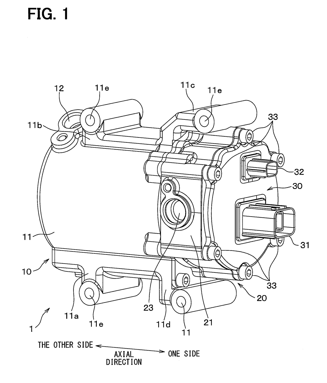
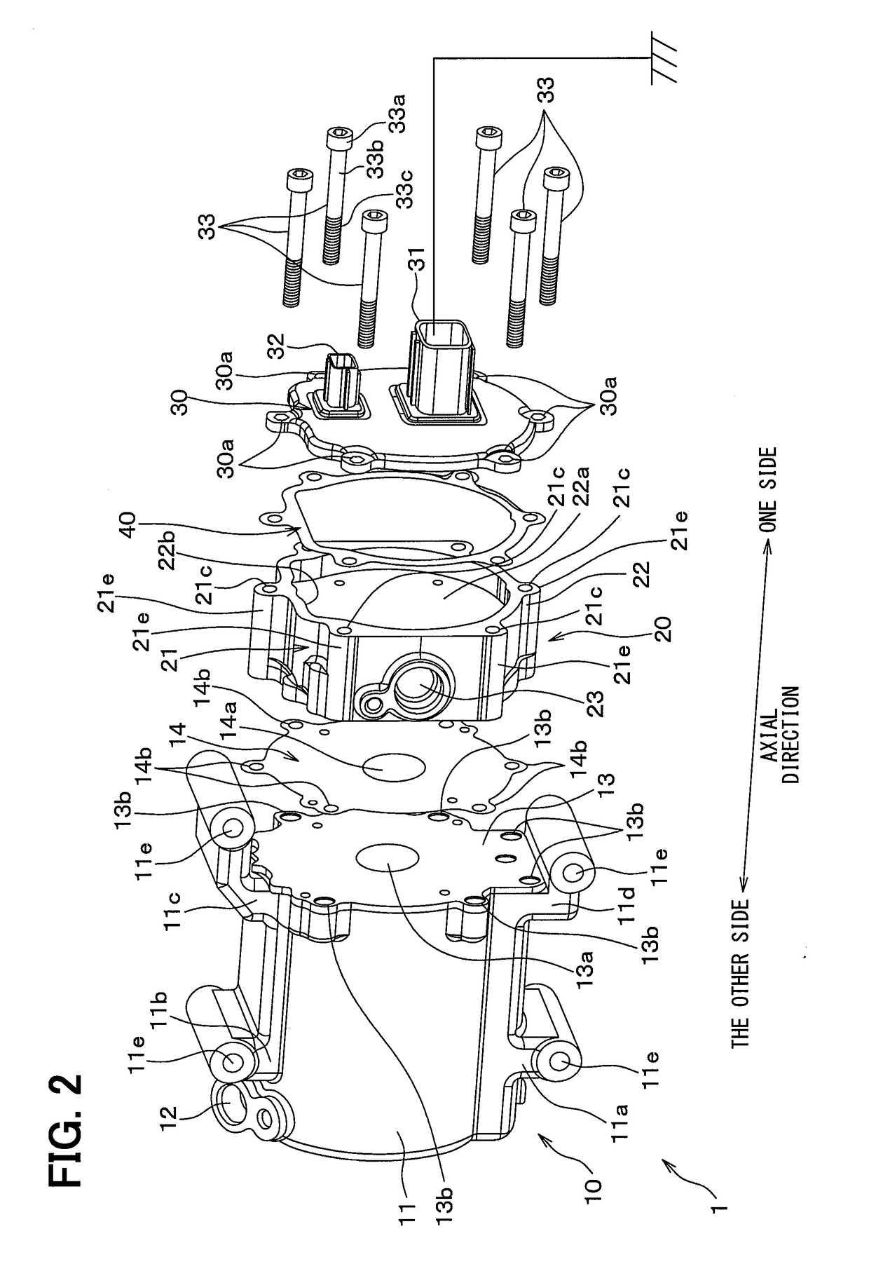
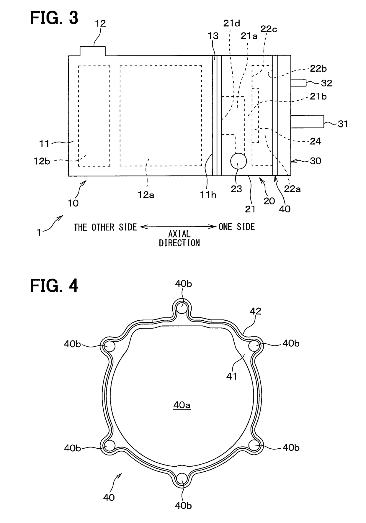
[0037]FIG. 1, FIG. 2, and FIG. 3 illustrate an electric compressor 1 for a vehicle according to a first embodiment.
[0038]The electric compressor 1 defines a refrigerating cycle equipment for a known in-vehicle air-conditioner in which refrigerant circulates, with a cooler, a reducing valve, and an evaporator. The electric compressor 1 is disposed in an engine room of a vehicle, and is fixed to an engine in the engine room.
[0039]As shown in FIG. 1 and FIG. 2, the electric compressor 1 includes a compressor part 10 and an inverter equipment 20. The compressor part 10 has a compressor case 11. The compressor case 11 has a pipe shape in which the other side in the axial direction is closed. A refrigerant discharge port 12 is formed in the other side of the compressor case 11 in the axial direction.
[0040]The compressor case 11 has legs 11a, 11b, 11c, and 11d. A through hole 11e is defined in the leg 11a, 11b, 11c, 11d, through which a bolt (not shown) passes. Four bolts passing through the
second embodiment
[0089]In the first embodiment, the electromagnetic wave noise propagating through the inverter case 21 is absorbed by the ground of vehicle, due to the electrical connection part 41 of the gasket 40. Alternatively, in a second embodiment, the electrical connection part 41 of the gasket 40 is replaced with a bolt 50 which fastens the inverter case 21 and the compressor case 11. The second embodiment is described with reference to FIG. 6 and FIG. 7.
[0090]The electric compressor 1 of this embodiment is defined by adding the bolt 50 to the electric compressor 1 of the first embodiment. As shown in FIG. 6 and FIG. 7, the bolt 50 is an electrical connection bolt fastened to a spiral hole 21g of the inverter case 21 through a spiral hole 11f of the leg 11c of the compressor case 11. The bolt 50 is made of metal and corresponds to a conductive component.
[0091]In this embodiment, the gasket 40 of FIG. 2 is replaced with a gasket 40A shown in FIG. 8 and FIG. 9.
[0092]The gasket 40A includes a met
third embodiment
[0103]In the second embodiment, the bolt 50 is used to make the ground of vehicle to absorb the electromagnetic wave noise propagating through the inverter case 21. Alternatively, in a third embodiment, the bolt 33 for fastening the inverter case 21 and the lid 30 onto the compressor case 11 is used. The third embodiment is described with reference to FIG. 11, FIG. 12A, FIG. 12B, and FIG. 13.
[0104]As shown in FIG. 11, each of the plural through-hole formation parts 21e of the compressor case 11 has an opening 21f open outward in the radial direction. In this embodiment, the opening 21f continuously extends in the axial direction.
[0105]In this embodiment, the gasket 40 of FIG. 2 is replaced with the gasket 40A shown in FIG. 8 and FIG. 9, similarly to the second embodiment.
[0106]The electric compressor 1 of this embodiment has the same configuration as the electric compressor 1 of the first embodiment, except for the plural through-hole formation parts 21e of the compressor case 11 and t
PUM
 Abstract
Description
Claims
Application Information
 - R&D Engineer
- R&D Manager
- IP Professional
- Industry Leading Data Capabilities
- Powerful AI technology
- Patent DNA Extraction
Browse by: Latest US Patents, China's latest patents, Technical Efficacy Thesaurus, Application Domain, Technology Topic.
© 2024 PatSnap. All rights reserved.Legal|Privacy policy|Modern Slavery Act Transparency Statement|Sitemap