Method of printing swaths of an image on a substrate

Active Publication Date: 2019-08-22
CANON PRODN PRINTING HLDG BV
View PDF2 Cites 0 Cited by
  • Summary
  • Abstract
  • Description
  • Claims
  • Application Information

AI Technical Summary

Benefits of technology

[0011]In a method according to the invention, a boundary between two adjacent swathes may be, but does not have to be a continuous straight line that extends in the main scanning direction from one edge of the substrate to the opposite edge. Instead, the position of the boundary in the sub-scanning direction may vary as a function of the position in the main scanning direction. This provides more freedom of choice for avoiding dark image areas where artefacts at the boundary would be clearly visible. For example, the image to be printed may be segmented into a number of columns of image pixels that extend in the sub-scanning direction and have a width of one or more pixels. Then, the position of the boundary in a given column may be determined independently of the boundary positions in other columns.
[0012]Several criteria and combinations of criteria may be applied for finding the best position for

Problems solved by technology

In certain applications it is difficult, however, to control the advance of the substrate wit

Method used


Image

  • Method of printing swaths of an image on a substrate
  • Method of printing swaths of an image on a substrate
  • Method of printing swaths of an image on a substrate

Examples


Embodiment Construction

[0022]The present invention will now be described with reference to the accompanying drawings, wherein the same or similar elements are identified with the same reference numeral.

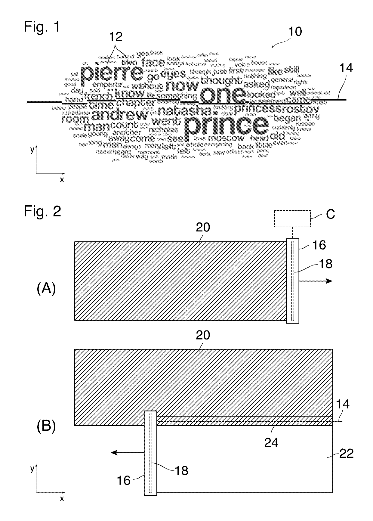
[0023]FIG. 1 shows an example of a portion of a printed image 10 that comprises, as image contents, a plurality of text elements 12 with different font sizes. In order to print the image 10, a print head is moved over a print substrate in a main scanning direction (x) in several subsequent scan passes, and a swath of the image 10 is printed in each pass. After each pass, the print substrate is advanced in a sub-scanning direction y by a distance corresponding to the width of the printed swath, so that another swath can be printed directly adjacent to the first swath. A boundary 14 between two adjacent swaths has been symbolized in FIG. 1 by a bold line that extends essentially in the main scanning direction x but is split into a plurality of straight segments that are slightly offset relative to one another in


PUM


Abstract

A printing method wherein a scanning-type printer, or a printer comprising a page-wide array of multiple printheads, is used for printing an image on a substrate in a plurality of adjacent swaths, the method comprising a step of determining positions of boundaries between the adjacent swaths on the basis of image contents to be printed, preferentially in such a way that artefacts are least likely to be visible.

Description


Claims


Application Information

Patent Timeline
Owner CANON PRODN PRINTING HLDG BV
Why Eureka
Try Eureka