Customizable wire harness form board sub-assembly structure having simple, quick-change wire routing exchange point capability

a wire harness and sub-assembly technology, which is applied in the direction of cable, cable connection, programme control, etc., can solve the problems of complex and detailed wire harness manufacturing, and achieve the effect of reducing the unit cost of the harness produced, increasing flexibility in routing, production and productivity

Active Publication Date: 2019-11-28
TILLOTSON JR JOHN D
View PDF0 Cites 0 Cited by
  • Summary
  • Abstract
  • Description
  • Claims
  • Application Information

AI Technical Summary

Benefits of technology

The technical effects of this patented invention aim to improve the efficiency and flexibility of wire harness assembly processes while reducing the cost per component. This involves managing multiple wires and lead parts with varying length sizes and placing them on specific locations within the assembly line. Additionally, it introduces a new way to make up and change the final assembly without having to move around large amounts of equipment.

Problems solved by technology

The technical problem addressed in this patent text relates to improving the efficiency and accuracy of producing high-quality electrical connections between separate wiring harnesses used in electronic device (ECD) applications. Manual adjustments and reconfiguration of fixture arrangements can be difficult due to the complexity involved. This results in increased labor costs and potential manufacture errors. Therefore, there is a desire to simplify the process of connecting wires to connectors and terminals without requiring excessive manual labor.

Method used


Image

  • Customizable wire harness form board sub-assembly structure having simple, quick-change wire routing exchange point capability
  • Customizable wire harness form board sub-assembly structure having simple, quick-change wire routing exchange point capability
  • Customizable wire harness form board sub-assembly structure having simple, quick-change wire routing exchange point capability

Examples


Embodiment Construction

[0037]While various aspects and features of certain embodiments have been summarized above, the following detailed description illustrates a few exemplary embodiments in further detail to enable one skilled in the art to practice such embodiments. The described examples are provided for illustrative purposes and are not intended to limit the scope of the invention.

[0038]In the following description, for the purposes of explanation, numerous specific details are set forth in order to provide a thorough understanding of the described embodiments. It will be apparent to one skilled in the art, however, that other embodiments of the present invention may be practiced without some of these specific details. Several embodiments are described herein, and while various features are ascribed to different embodiments, it should be appreciated that the features described with respect to one embodiment may be incorporated with other embodiments as well. By the same token, however, no single featur


PUM


Abstract

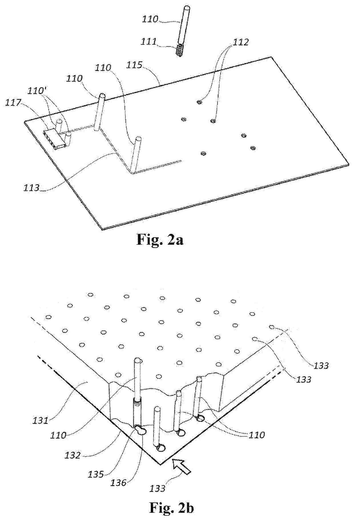
A floating pin form board assembly to aid wire harness assembly includes a first embodiment with a work block and chambers containing floating pegs which may reside in retracted or extended positions based on perforations in a wire routing form sheet which allow or prevent retracted pegs from rising to extended positions. Extended pegs may be locked into their extended positions by means of a slidable latch plate, and stop features in the pegs prevent them from escaping past their extended positions.
Alternatively, a floating peg form board assembly includes a perforated sheet and first, second, plates third plates each having apertures spaced apart in congruent arrays and a plurality of floating pegs having stop features, and a slidable latch plate having an array of keyhole slots complementary to apertures in one of the other perforated plates, with the latch plate used for locking the floating pegs into retracted or extended positions.

Description


Claims


Application Information

Patent Timeline
Owner TILLOTSON JR JOHN D
Why Eureka
Try Eureka