Easy-to-mount actuator

Active Publication Date: 2020-03-12
SAFRAN ELECTRONICS & DEFENSE
View PDF0 Cites 0 Cited by
  • Summary
  • Abstract
  • Description
  • Claims
  • Application Information

AI Technical Summary

Benefits of technology

[0007]Thus, the angular amplitude of less than one revolution and the arrangement of the transmission line for allowing only one angular position between the inlet pinions makes the actuator easier to assemble and to maintain.

Problems solved by technology

That solution is relatively complex, in particular because it is necessary for the shafts to be set angularly relative to one another in order to ensure that the actuator members acting on a common flight control surface are synchronized.
Unfortunately, the actuator system is so arranged that actuating the flight control surfaces between their extreme positions requires the shafts to turn through more than one revolution: a given angular position of a shaft can thus correspond to a plurality of positions of the flight control surfaces.
That greatly complicates initial assembly of the actuator system and also subsequent maintenance operations.
This results in relatively large weight for the actuator system as a whole.

Method used


Image

  • Easy-to-mount actuator
  • Easy-to-mount actuator
  • Easy-to-mount actuator

Examples


Example

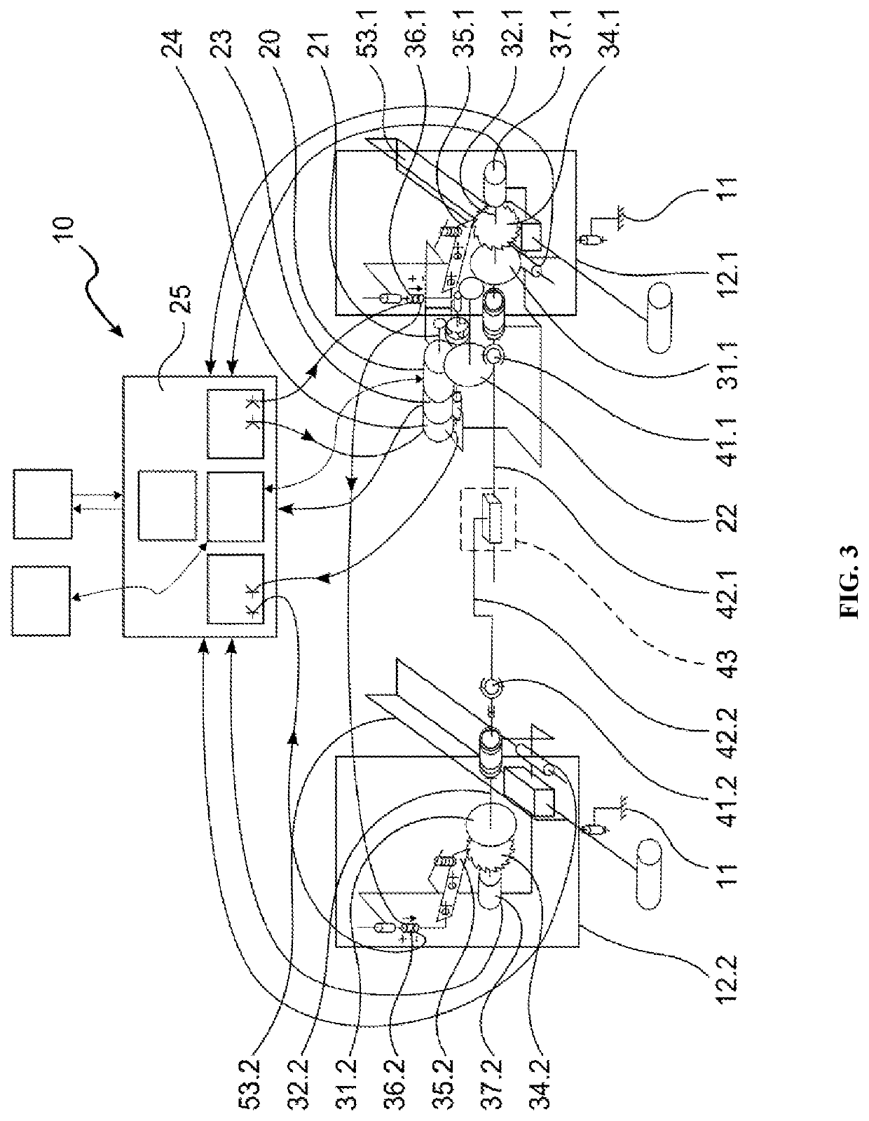
[0029]The operation of the actuator 10 in the second embodiment is otherwise identical to the operation of the first embodiment.

[0030]Naturally, the invention is not limited to the embodiments described but covers any variant coming within the definition of the invention that appears in the claims.

[0031]In particular, the invention is applicable to actuating any flight control surface, and for example ailerons, rudders, flaps, slats, elevators, . . . .

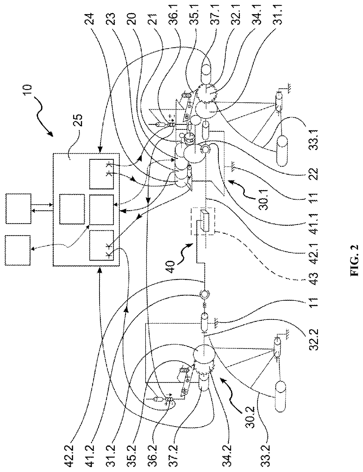
[0032]The computers of the control unit 5 may be centralized or they may be distributed between a central unit situated in the vicinity of the cockpit of the aircraft for centralizing processing of piloting instructions coming from the cockpit, and dedicated units connected to the central unit and arranged closer to the actuators 10 in order to control them as a function of commands generated by the central unit on the basis of the piloting instructions.

[0033]The racks may be replaced by ball screws.

[0034]The coupling 43 may be provided b


PUM


Abstract

An actuator for at least one flight control surface of an aircraft. The actuator has at least two actuator members for actuating the flight control surface between two extreme positions and a motor connected to the actuator members by at least one rotary motion transmission line. Each actuator member includes a drive pinion and the actuator is arranged so that the transmission line has an angular amplitude of less than one revolution during movement of the flight control surface between its two positions. The motion transmission line is arranged to allow only one angular position between the drive pinions and the actuator member.

Description


Claims


Application Information

Patent Timeline
Owner SAFRAN ELECTRONICS & DEFENSE
Why Eureka
Try Eureka