Wind generating set

A technology for wind turbines and connecting components, which is applied to wind turbines, wind energy power generation, engines, etc., can solve the problems of high manufacturing cost, uneven stress distribution, and difficult assembly, and achieve easy manufacturing, force distribution optimization, Solve the effect of uneven stress

Active Publication Date: 2018-05-08
XINJIANG GOLDWIND SCI & TECH
View PDF4 Cites 0 Cited by
  • Summary
  • Abstract
  • Description
  • Claims
  • Application Information

AI Technical Summary

Problems solved by technology

[0006] Therefore, the object of the present invention is to provide a kind of wind generating set, to overcome the problems such as uneven stress distribution, high manufacturing cost, difficult assembly, etc. that exist when the rotating shaft of the wind generating set is connected to the hub in the prior art.

Method used


Image

  • Wind generating set
  • Wind generating set
  • Wind generating set

Examples


Example Embodiment

[0034] Now, embodiments in accordance with the present invention will be described in detail with reference to the accompanying drawings, examples of which are illustrated in the accompanying drawings, wherein like reference numerals refer to like components throughout.

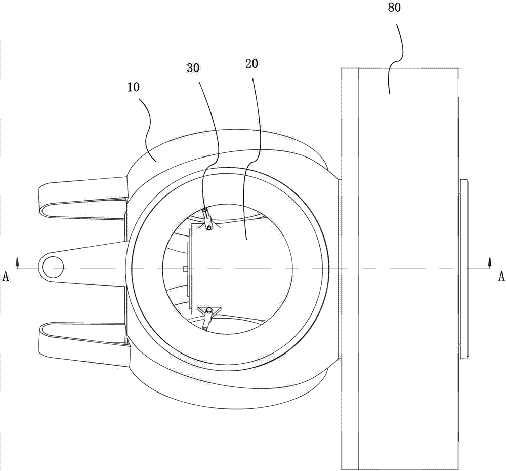
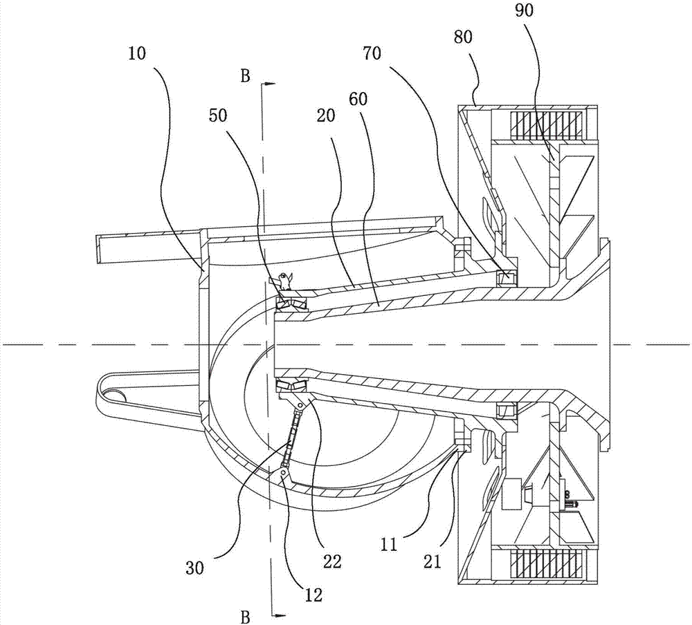
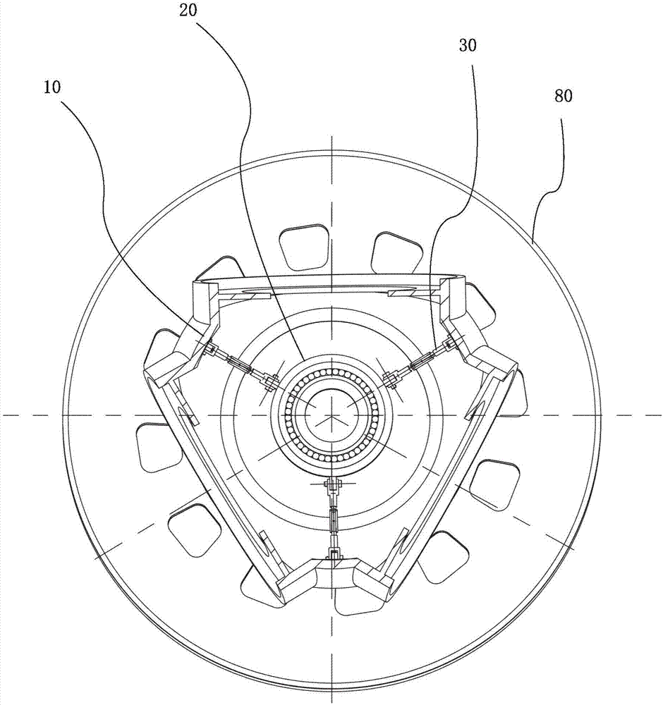
[0035] figure 1 It is a schematic diagram of the partial structure of the wind turbine according to the first embodiment of the present invention. figure 2 is along the figure 1 A cross-sectional view taken on line A-A. image 3 is along the figure 2 A cross-sectional view taken from the B-B line.

[0036] Below, will refer to Figure 1 to Figure 3 The structure of the wind turbine according to the first embodiment of the present invention is described in detail.

[0037] like figure 1 and figure 2 As shown, the wind turbine according to the first embodiment of the present invention may include a hub 10 , a rotating shaft 20 , a rod-shaped connecting assembly 30 , a front bearing 50 , a fixed shaft 60


PUM


Abstract

The invention provides a wind generating set. The wind generating set comprises a hub, a rotary shaft and a plurality of rod-shaped connecting assemblies, wherein a first connecting flange is formed on the end surface of the hub; one end of the rotary shaft is inserted into the hub, a second connecting flange is formed on the outer surface of the rotary shaft, and the second connecting flange is connected to the first connecting flange; and the two ends of each rod-shaped connecting assembly are separately connected to the rotary shaft and the hub. According to the wind generating unit provided by the invention, connection between the rotary shaft and the hub can be realized through the first connecting flange, the second connecting flange and the rod-shaped connecting assemblies, and stress at the first connecting flange and the second connecting flange can be reduced, so that connecting rigidity and strength between the hub and the rotary shaft is strengthened, and stress distribution is optimized, and therefore, impact resistance of a connecting structure for the hub and the rotary shaft can be strengthened.

Description


Claims


Application Information

Patent Timeline
Owner XINJIANG GOLDWIND SCI & TECH
Why Eureka
Try Eureka