Auxiliary electrode structure for large-scale grounding grid ground resistance measurement

A technology of grounding resistance and auxiliary electrode, applied in the field of auxiliary electrode structure, can solve problems such as poor grounding of auxiliary electrodes, and achieve the effects of overcoming poor grounding effect, being convenient to carry, and improving measurement efficiency.

Active Publication Date: 2016-11-02
STATE GRID CORP OF CHINA +2
View PDF11 Cites 2 Cited by
  • Summary
  • Abstract
  • Description
  • Claims
  • Application Information

AI Technical Summary

Problems solved by technology

The invention can solve the problem of poor grounding of the existing auxiliary electrodes, reduce test interference, improve test accuracy, and is more convenient to install and use

Method used


Image

  • Auxiliary electrode structure for large-scale grounding grid ground resistance measurement

Examples


Example Embodiment

[0015] The present invention will be further described below in conjunction with the drawings and embodiments, but it is not a basis for limiting the present invention.

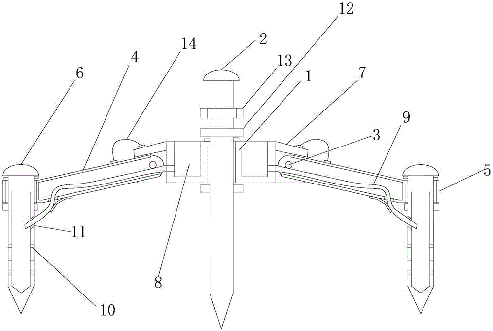
[0016] Examples. Auxiliary electrode structure for ground resistance measurement of large grounding grid, such as figure 1 As shown in Figure 2: It includes a center bracket 1 made of metal. The center bracket 1 is provided with a positioning hole in the center, and a center metal pile 2 is arranged in the positioning hole. The outer side of the center bracket 1 is connected with 6 evenly distributed pins 3 through 6 rotating pins. The support arms 4 made of metal are connected; the end of each support arm 4 is provided with a positioning sleeve 5, and a side metal pile 6 is provided in the positioning sleeve 5. The connection between the central support 1 and the support arm 4 is provided with a limit frame 7 that limits the maximum opening angle of the support arm 4 to less than 90° (in use, the support arm 4 is


PUM

PropertyMeasurementUnit
Diameteraaaaaaaaaa
Lengthaaaaaaaaaa

Abstract

The invention discloses an auxiliary electrode structure for large-scale grounding grid ground resistance measurement. The auxiliary electrode structure is characterized by comprising a central support rack (1) made of metal material, wherein the center of the central support rack (1) is provided with a positioning hole, a central metal post is arranged in the positioning hole, an outer side of the central support rack (1) is connected with six uniformly distributed support arms (4) made of metal material via six rotating pins (3), an end part of each support arm (4) is provided with a positioning sleeve cylinder (5), and a side edge metal post (6) is arranged in each positioning sleeve cylinder (5). The auxiliary electrode structure can help solve a problem of poor ground connection of a conventional auxiliary electrode, test interference can be lowered, test precision can be improved, and convenience of installation and utilization can be improved.

Description


Claims


Application Information

Patent Timeline
Owner STATE GRID CORP OF CHINA
Why Eureka
Try Eureka