Work support system

a multi-functional, work platform technology, applied in metal-working machine components, metal-working apparatus, manufacturing tools, etc., can solve problems such as inefficiency, damage to work surfaces, objects, etc., and achieve the effect of improving work efficiency, reducing work difficulty, and reducing work spa

Pending Publication Date: 2020-07-16
PREDDIS
View PDF0 Cites 0 Cited by
  • Summary
  • Abstract
  • Description
  • Claims
  • Application Information

AI Technical Summary

Benefits of technology

The patented technology allows for easy assembly of a work support system that includes various parts like a base, a cover, and work support components. This makes it easier to install on different types of equipment without having to purchase multiple tools.

Problems solved by technology

The technical problem addressed in this patent text relates to improving the efficiency and effectiveness of applying surface coatings onto objects while reducing their exposure time and preventing unwanted touch points from entering. Current solutions involve either wetting the entire surface before applying the coatings, or adding extra steps like sand blasting to remove any excessive material. Additionally, current methods of attaching objects to a surface using screw clamps or bolts can result in contaminations due to contact between the objects and the surface being treated.

Method used


Image

  • Work support system
  • Work support system
  • Work support system

Examples


Embodiment Construction

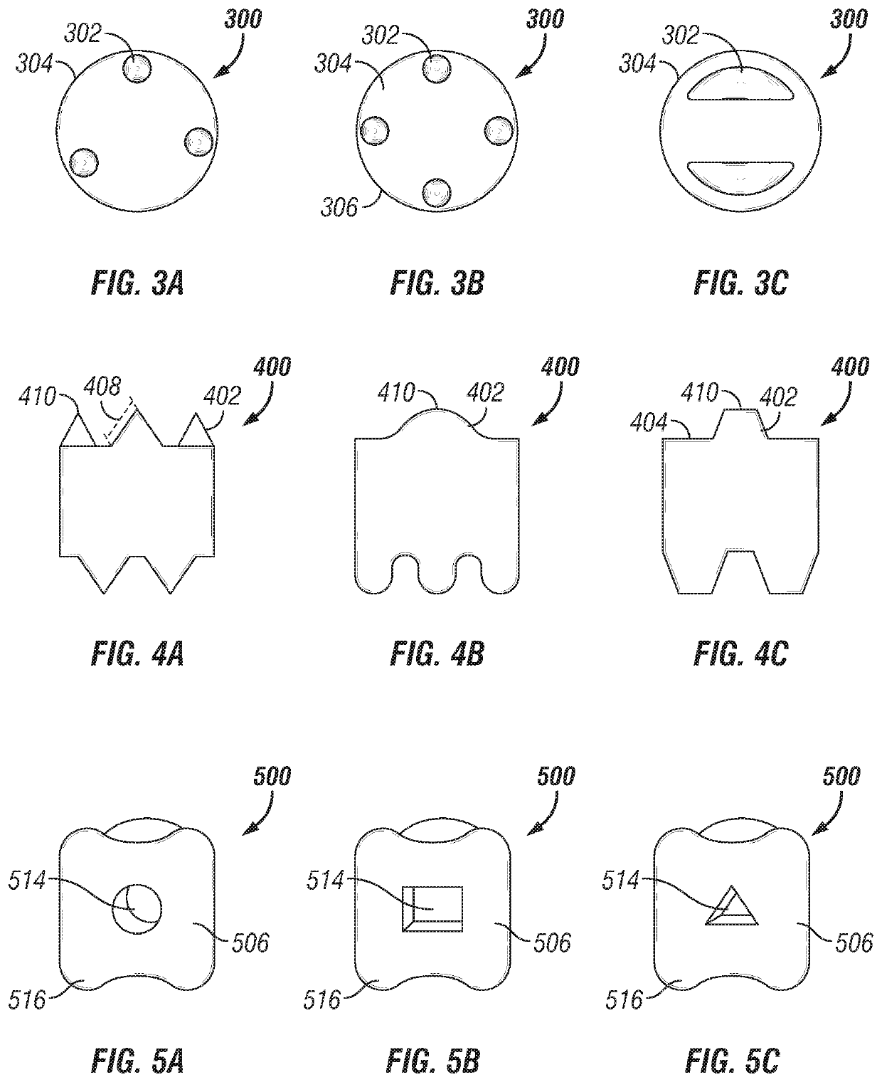
[0038]As shown in FIGS. 3A-3C, embodiments of a work stand 300 may include various configurations of supports 302 on a support surface 304 thereof. Such supports 302 may have a generally circular cross section (FIGS. 3A-3B), a semi-circular cross section (FIG. 3C) or various other cross-sectional configurations such as a triangular / wedge configuration, etc.

[0039]In various embodiments, supports 302 may vary in width and cross-section as they extend away from the support surface 304. In various embodiments, the supports 302 may also be configured to mate with similar or dissimilar supports on a second work stand 300, such that a plurality of such work stands 300 may be securely stacked to achieve a desired height.

[0040]In various embodiments, supports 302 are generally spaced substantially equidistantly upon the support surface 304 to provide for an improved balance to a supported object. In one embodiment, the supports 302 will typically be disposed along or near a periphery of the s


PUM


Abstract

A work stand includes upper and lower surfaces, the upper surface configured to support an object in a balanced manner above the work stand, and the lower surface configured to rest stably upon a work surface. Supports may be integrated into or attachable to the upper surface and may be selected to provide a predetermined support to the object, such support having an element of height and manner of contact with the object. Each support terminates in an apex which may be configured as a rounded, tapered, or flat configuration. The system may be utilized by placement upon a work surface and then placing an object upon an apex or ridge thereof, to support the object above the work surface.

Description


Claims


Application Information

Patent Timeline
Owner PREDDIS
Why Eureka
Try Eureka