Free electron laser orbital debris removal system

a free electron laser and orbital debris technology, applied in the direction of optical resonator shape and construction, transportation and packaging, and cosmonautic vehicles, can solve the problems of prior odr solutions that have not been effective at dealing with category ii od, lasers typically do not have the diffraction limited beam quality, etc., to achieve the effect of improving the signal-to-noise ratio

Pending Publication Date: 2020-09-17
BNNT
View PDF6 Cites 1 Cited by
  • Summary
  • Abstract
  • Description
  • Claims
  • Application Information

AI Technical Summary

Benefits of technology

This patented technology describes different ways to remove or reduce damage caused by space objects such as satellites that are orbiting around them during flight. One method involves using special equipment called optical fibers (OFLs) placed on top of each object's surface. These fiber devices can transmit laser lights towards these areas where they hit due to their small size and high intensity. By measuring how well this reflection occurs, it becomes possible to determine if there were any other things like dents near those points being impacted onto the satellite itself.

Problems solved by technology

This technical problem addressed in this patents relating to improving the efficiency of detecting Object Density Units (called DECUs) such as Group IV ions without damaging their properties during detection processes like optical scanning. Current methods require powerful sources, including ion guns, atomic massistors, and even higher energy electronequids (EML)). These techniques also suffer limitations when trying to reach long distances.

Method used


Image

  • Free electron laser orbital debris removal system
  • Free electron laser orbital debris removal system
  • Free electron laser orbital debris removal system

Examples


Embodiment Construction

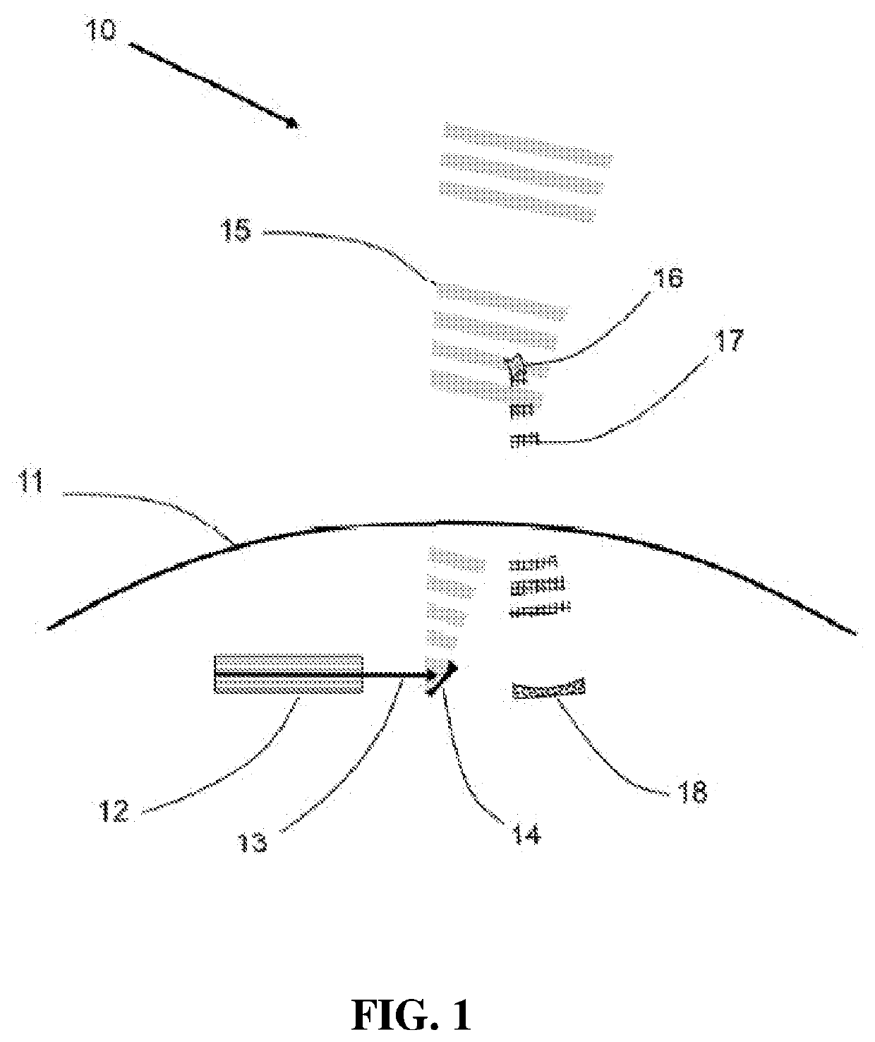
lass="d_n">[0032]Described herein are embodiments of FEL ODR systems and methods capable of average power, peak power light pulses, and temporal and spatial resolution combinations, to both locate and remove OD, and particularly Category II OD in some embodiments. Category II OD typically has diameters in the 1 to 10 cm range. Category I is OD10 cm. As will be appreciated by those of ordinary skill in the art, embodiments of an FEL ODR system under the present approach can also remove OD in Category I and Category III. A variety of FEL formats are possible, including Oscillator (OSC) FEL as used for the Jefferson Lab 14 kW FEL, Self-Amplified Spontaneous Emission (SASE) FEL which operates as an Amplifier (AMP) of noise, Regenerative Amplifier FEL (RAFEL), Master Oscillator / Power Amplifier (MOPA) FEL, and optical klystron FEL.

[0033]FIG. 1 illustrates an embodiment of an FEL ODR system 10 located on the surface of the Earth 11. The system may be used to locate OD 16. The FEL 12 is, in


PUM


Abstract

Orbital debris removal (ODR) systems under the present approach may use a ground- or surface-based FEL and mirror system with sufficient power and both spatial and temporal resolution to both locate Category II OD (1 cm to 10 cm diameter) in low Earth orbit (LEO, 160 to 2000 km altitude) and remove these objects from orbit. Locating the Category II OD is performed by having the light beam from an FEL and its beam director scan a volume of space of interest and then observing the light reflected from the OD. Removing the OD may include heating the OD to a sufficiently high temperature to evaporate the OD, changing the orbit of the OD such as to lower the perigee, or both. Megawatt-class MOPA FELs for, inter alia, removing OD, are described.

Description


Claims


Application Information

Patent Timeline
Owner BNNT
Why Eureka
Try Eureka