Consistently editing light field data

a technology of light field data and editing, applied in the field of light field imaging, can solve the problems of low light field data quality, low light field quality, and low light field quality, and achieve the effects of improving light field quality, and improving light field quality

Inactive Publication Date: 2020-12-31
INTERDIGITAL CE PATENT HLDG
View PDF0 Cites 2 Cited by
  • Summary
  • Abstract
  • Description
  • Claims
  • Application Information

AI Technical Summary

Benefits of technology

The present technology helps reduce any mistakes made during depth mapping because it uses accurate measurements from different sources for calculating its distance towards objects within an image frame. This reduces errors caused by factors like imperfections or variations over time such as temperature changes.

Problems solved by technology

Technological Problem: Current Optical Field Capture Devices (OCD' s) only allow for precise adjustments of focus settings based upon spatial coordinates rather than just intensity values alone. They lack detailed analysis capabilities like how well they work when zooming into specific areas where there might exist multiple perspectives. Additionally, current solutions involve complicated calculations involving matrix operations, requiring significant computational resources.

Method used


Image

  • Consistently editing light field data
  • Consistently editing light field data
  • Consistently editing light field data

Examples


Embodiment Construction

[0063]General concepts and specific details of certain embodiments of the disclosure are set forth in the following description and in FIGS. 1 to 5 to provide a thorough understanding of such embodiments. Nevertheless, the present disclosure may have additional embodiments, or may be practiced without several of the details described in the following description.

5.1 General Concepts and Prerequisites

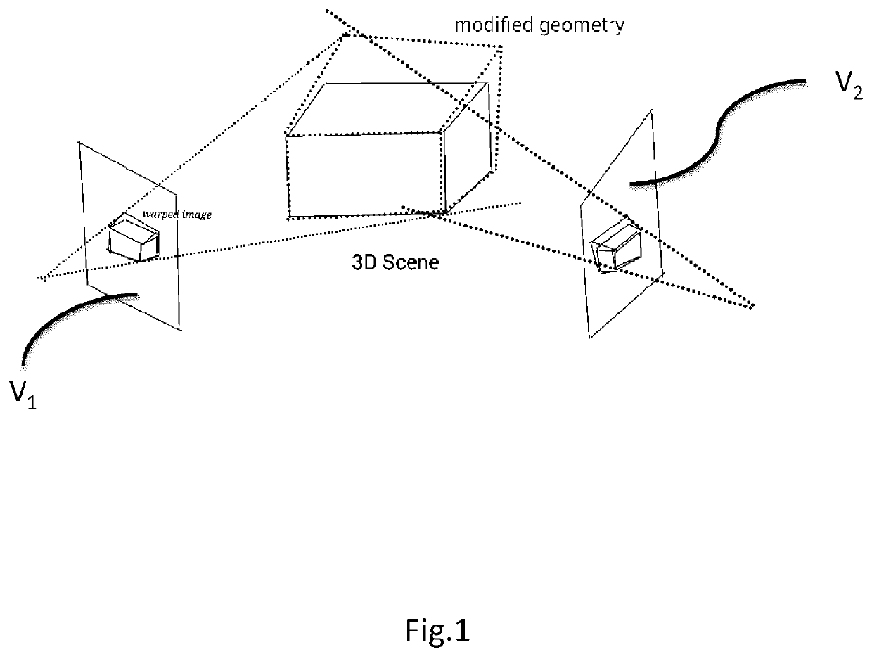
[0064]The invention describes a method for propagating a geometric warp specified by positional constraints on some of the views of a light-field capture, the reference views, to all the views and generating a warped image for each view, in such a way that the warped images are geometrically consistent in 3D across views.

[0065]We assume that the light field is given by a set of views V={Vm} which sample the viewing angle under which the scene is captured, as illustrated by FIG. 1.

[0066]This set V of views Vm comprises at least two reference views Vj and at least one additional view Vk.

[0067


PUM


Abstract

The invention describes a method for applying a geometric warp to the light field capture of a 3D scene, consisting of several views of the scene taken from different viewpoints. The warp is specified as a set of (source point, target point) positional constraints on a subset of the views. These positional constraints are propagated to all the views and a warped image is generated for each view, in such a way that these warped images are geometrically consistent in 3D across the views.

Description


Claims


Application Information

Patent Timeline
Owner INTERDIGITAL CE PATENT HLDG
Why Eureka
Try Eureka