Systems and methods for supplying low salinity injection water

a technology of low salinity and injection water, which is applied in the direction of multi-stage water/sewage treatment, membranes, borehole/well accessories, etc., can solve the problems of inability to recover oil, reduce the amount of produced water, and reduce the effect of production

Pending Publication Date: 2022-01-13
BP EXPLORATION OPERATING CO LTD
View PDF0 Cites 1 Cited by
  • Summary
  • Abstract
  • Description
  • Claims
  • Application Information

AI Technical Summary

Benefits of technology

The present invention relates to an integrated system used in saltwater purification systems. It includes two main components: a desalination system and a filter system. These components work together to remove impurities from sea water. One component called the desalination system produces high quality water while another component called the filter system separates out unwanted substances from the remaining liquid. This allows for efficient use of resources such as electricity and fuel.

Problems solved by technology

This patent describes a technical problem related to low salt water flooding in oil-bearing formations due to the presence of excessive water injections. These injected waters can cause damage to the oil-bearing rocks and lead to corrosion. To address this issue, various methods have been developed to control the amount of water used for injection purposes. However, these methods are often limited because they only work at certain concentrations and cannot account for variations in production rates. Therefore, it would be useful to develop a method that can adjust the appropriate salinity for different types of injection water based on factors like temperature and pressure conditions.

Method used


Image

  • Systems and methods for supplying low salinity injection water
  • Systems and methods for supplying low salinity injection water
  • Systems and methods for supplying low salinity injection water

Examples


Embodiment Construction

[0021]The following discussion is directed to various exemplary embodiments. However, one skilled in the art will understand that the examples disclosed herein have broad application, and that the discussion of any embodiment is meant only to be exemplary of that embodiment, and not intended to suggest that the scope of the disclosure, including the claims, is limited to that embodiment.

[0022]Certain terms are used throughout the following description and claims to refer to particular features or components. As one skilled in the art will appreciate, different persons may refer to the same feature or component by different names. This document does not intend to distinguish between components or features that differ in name but not function. The drawing figures are not necessarily to scale. Certain features and components herein may be shown exaggerated in scale or in somewhat schematic form and some details of conventional elements may not be shown in the interest of clarity and conci


PUM


Abstract

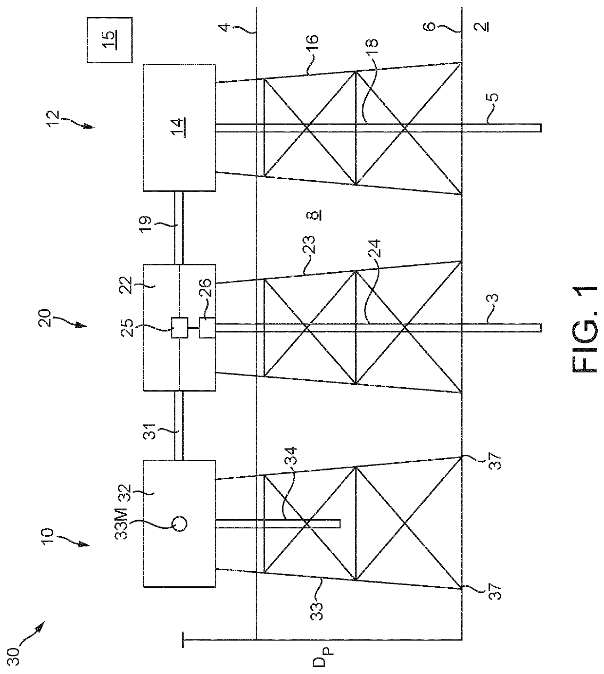
A desalination system includes a desalination platform, a first skid disposed on a first deck of the desalination platform, the first skid including at least one of a first filtration unit configured to produce a first filtrate stream, and a first permeate unit configured to produce a first permeate stream, a first interconnecting pipework coupled to the first skid, and a first pipework support disposed on the first deck, wherein the first interconnecting pipework is disposed on the first pipework support.

Description


Claims


Application Information

Patent Timeline
Owner BP EXPLORATION OPERATING CO LTD
Why Eureka
Try Eureka