Engine cylinder head coolant jacket

Inactive Publication Date: 2000-06-06
YAMAHA MOTOR CO LTD
View PDF16 Cites 4 Cited by
  • Summary
  • Abstract
  • Description
  • Claims
  • Application Information

AI Technical Summary

Problems solved by technology

Conventionally, the cylinder head has been manufactured by casting, thus necessitating complicated manufacturing processes to cast the passa

Method used


Image

  • Engine cylinder head coolant jacket
  • Engine cylinder head coolant jacket
  • Engine cylinder head coolant jacket

Examples


Embodiment Construction

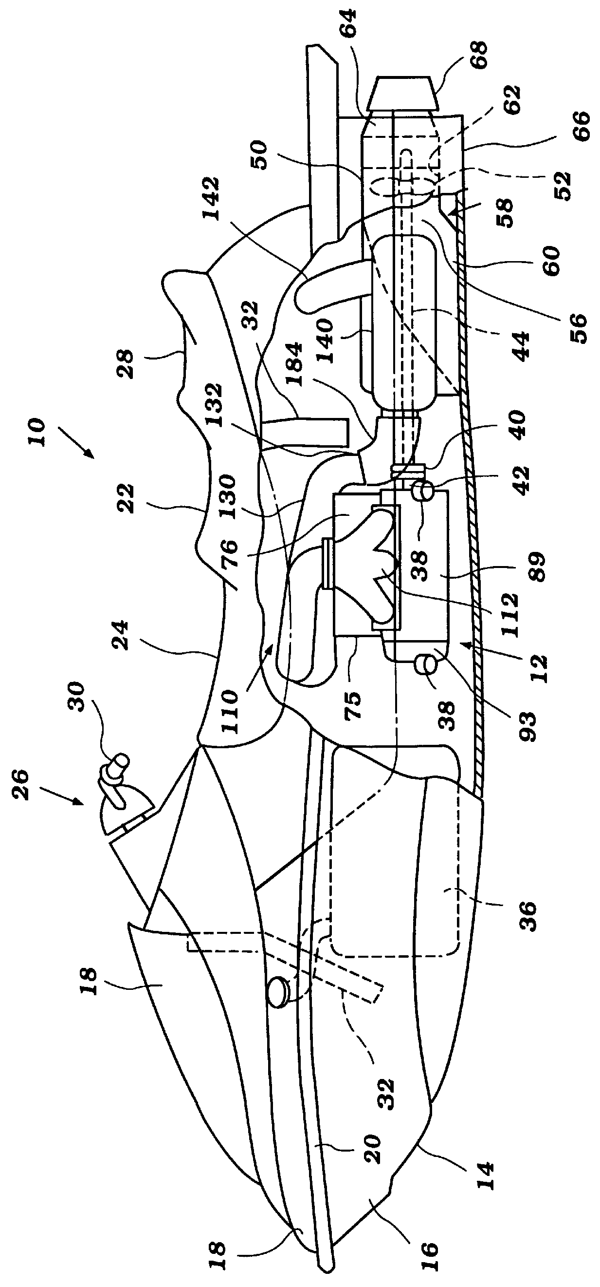
FIG. 1 illustrates a personal watercraft 10 which includes a marine engine 12 configured in accordance with a preferred embodiment of the present invention. Although the present engine 12 is illustrated in connection with a personal watercraft, the engine 12 can be used with other types of watercraft as well, such as, for example, but without limitation, small jet boats and the like.

Before describing the engine 12, an exemplary personal watercraft 10 will first be described in general details to assist the reader's understanding of the environment of use and the operation of the engine 12. The watercraft 10 includes a hull 14 formed by a lower hull section 16 and an upper deck section 18. The hull sections 16, 18 are formed from a suitable material such as, for example, a molded fiberglass reinforced resin. The lower hull section 16 and the upper deck section 18 are fixed to each other around the peripheral edge 20 in any suitable manner.

A passenger seat 22 is provided proximate to the


PUM


Abstract

A multiple cylinder engine for a small watercraft is provided with a separately structured cylinder head and cylinder head cover which cooperate when fastened together to define a cylinder head water jacket with chambers for cooling each cylinder in the engine. A longitudinally oriented coolant passage runs past and communicates with each water jacket chamber to facilitate flow of cooling water out of each chamber. In an embodiment in which the cylinders are inclined, the coolant passage is positioned in a higher location than the water jacket chambers.

Description


Claims


Application Information

Patent Timeline
Owner YAMAHA MOTOR CO LTD
Why Eureka
Try Eureka