Fastening element

a technology of fastening elements and fastening parts, which is applied in the direction of identification means, instruments, seals, etc., can solve the problems of jamming condition of fastening elements attached to guns, various difficulties for operators, and malfunction of attaching guns b>10/b>

Inactive Publication Date: 2005-02-01
KOTECS +1
View PDF6 Cites 2 Cited by
  • Summary
  • Abstract
  • Description
  • Claims
  • Application Information

AI Technical Summary

Benefits of technology

The present invention provides a new design for fasteners used in electronic devices. It uses multiple units of threaded material together like threads, inserts, and sockets. Each unit has its own unique shape and positioning, allowing it to connect to different parts of the device more easily than traditional methods. This results in better performance and durability compared to existing designs.

Problems solved by technology

The technical problem addressed in this patent is how to efficiently attach and detach fastening elements onto different types of attachment guns without interfering with their functioning components, particularly those associated with the thread forming process. This is because the existing methods require manual manipulation and may result in jamming conditions requiring additional steps. Additionally, the current methods involve bulky packages that take longer than desired times to set up and disconnect.

Method used


Image

  • Fastening element
  • Fastening element
  • Fastening element

Examples


Embodiment Construction

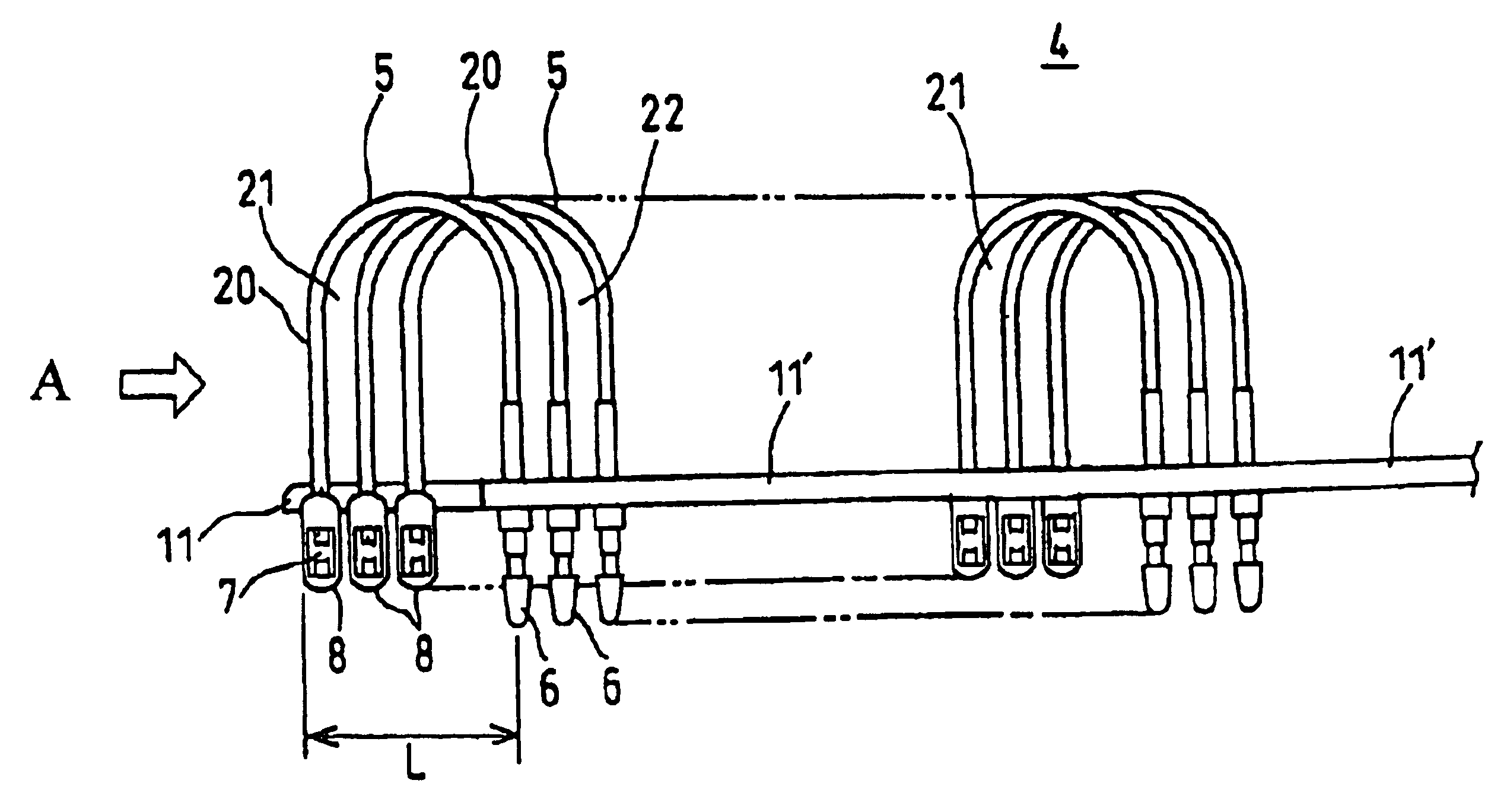
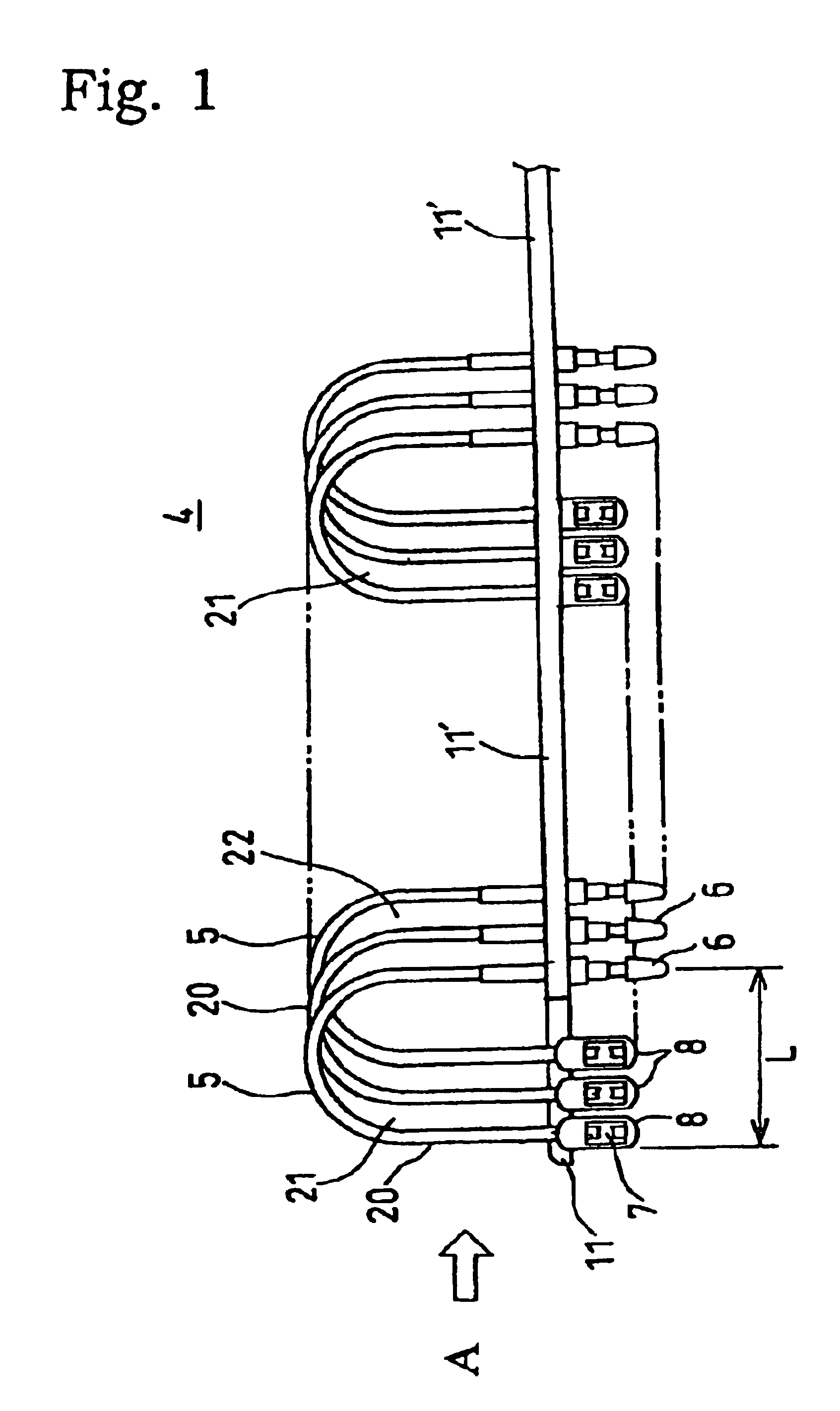
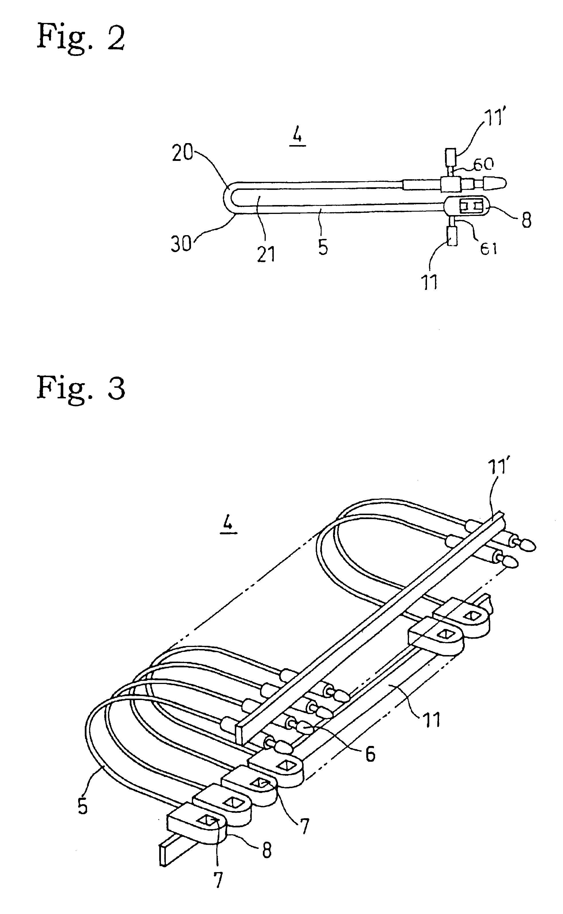
As mentioned above, the fastening element according to the present invention is characterized in that a fastening element comprising a plurality of a unit fastening element arranged adjacently and in parallelism with each other, each of the unit fastening element comprising a filament section, an inserting head section equipped with a suitable engagement section located at one end of the filament section, and a socket section equipped with a hole for irreversibly passing the inserting head section located at the other end of the filament section, the fastening element characterized in that a plurality of the socket sections or their vicinities each being adjacently arranged to each other and a plurality of the inserting head sections or their vicinities each being adjacently arranged to each other, are temporarily and individually connected to each one of connection bars, respectively, and further each of the connection bars are closely arranged to each other so as to be oppositely dis


PUM


Abstract

A plurality of fastening elements are arranged parallel to each other, each of the unit fastening elements having a filament section, an inserting head section equipped with a suitable engagement section at one end, and a socket section equipped with a hole for irreversibly passing the inserting head section located at the other end. The socket sections arranged on one connection bar, and the inserting head sections are arranged on another connection bar. The connection bars are closely arranged to each other so as to be oppositely disposed to each other with a predetermined length displaced to each other along a longitudinal direction of the bars. The filament section of each one of the unit fastening elements is formed in a curved configuration which is in fixed condition, so jamming is reduced when the operator couples the fastening element using a coupler gun.

Description


Claims


Application Information

Patent Timeline
Owner KOTECS
Why Eureka
Try Eureka