Safety switch with unlatching disc

Inactive Publication Date: 2005-03-01
EUCHNER GMBH & CO KG
View PDF6 Cites 14 Cited by
  • Summary
  • Abstract
  • Description
  • Claims
  • Application Information

AI Technical Summary

Benefits of technology

An object of the present invention is providing a safety switch ensuring long-term handling reliability.

Problems solved by technology

In the event the application of a strong force, the danger exists that the circumferential surface of the switching disk may be damaged by the locking element.
Disadvantageously, the locking element is moved directly by the actuator to be introduced, diminishing the reliability of handling.

Method used


Image

  • Safety switch with unlatching disc
  • Safety switch with unlatching disc
  • Safety switch with unlatching disc

Examples


Example

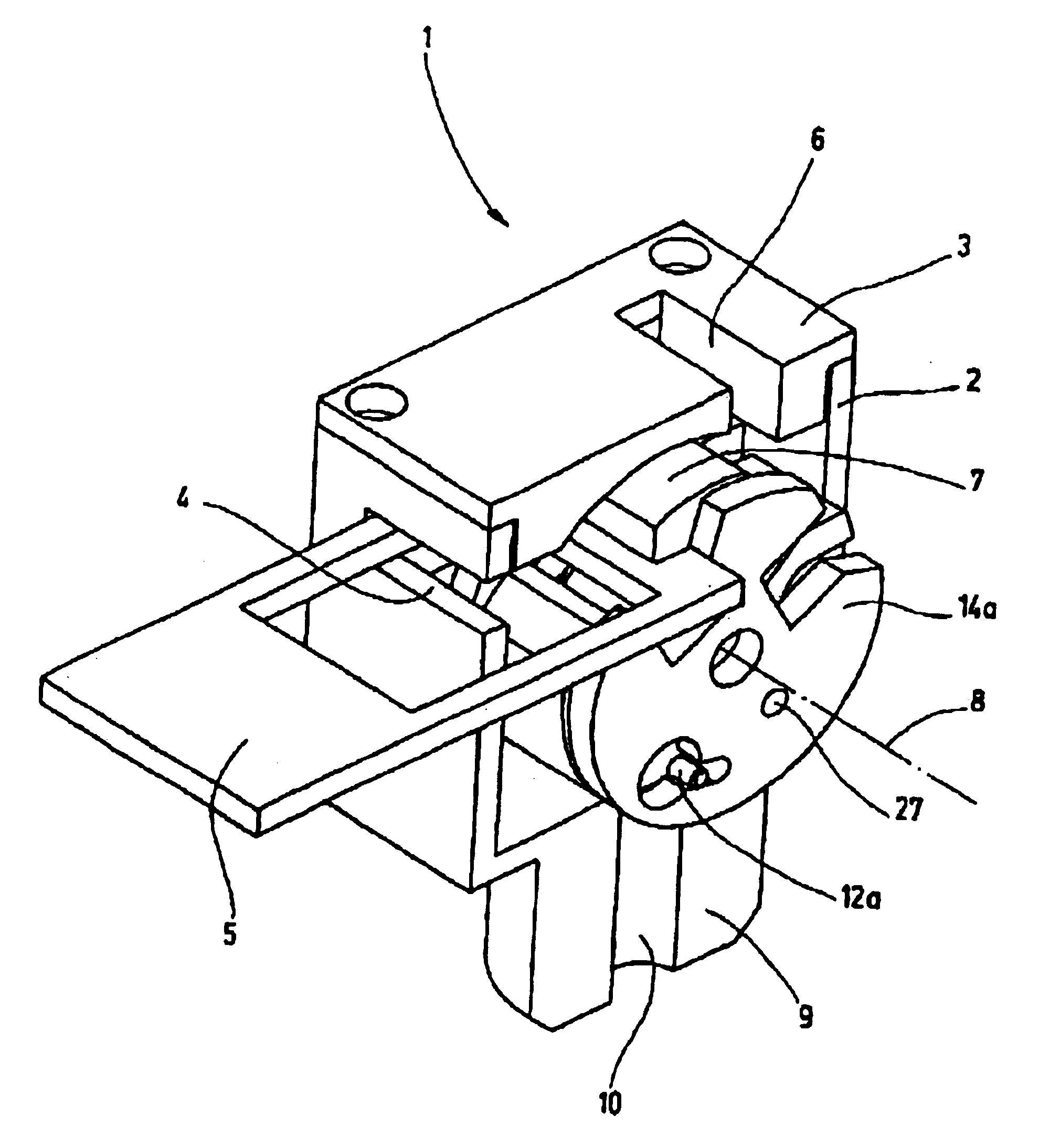
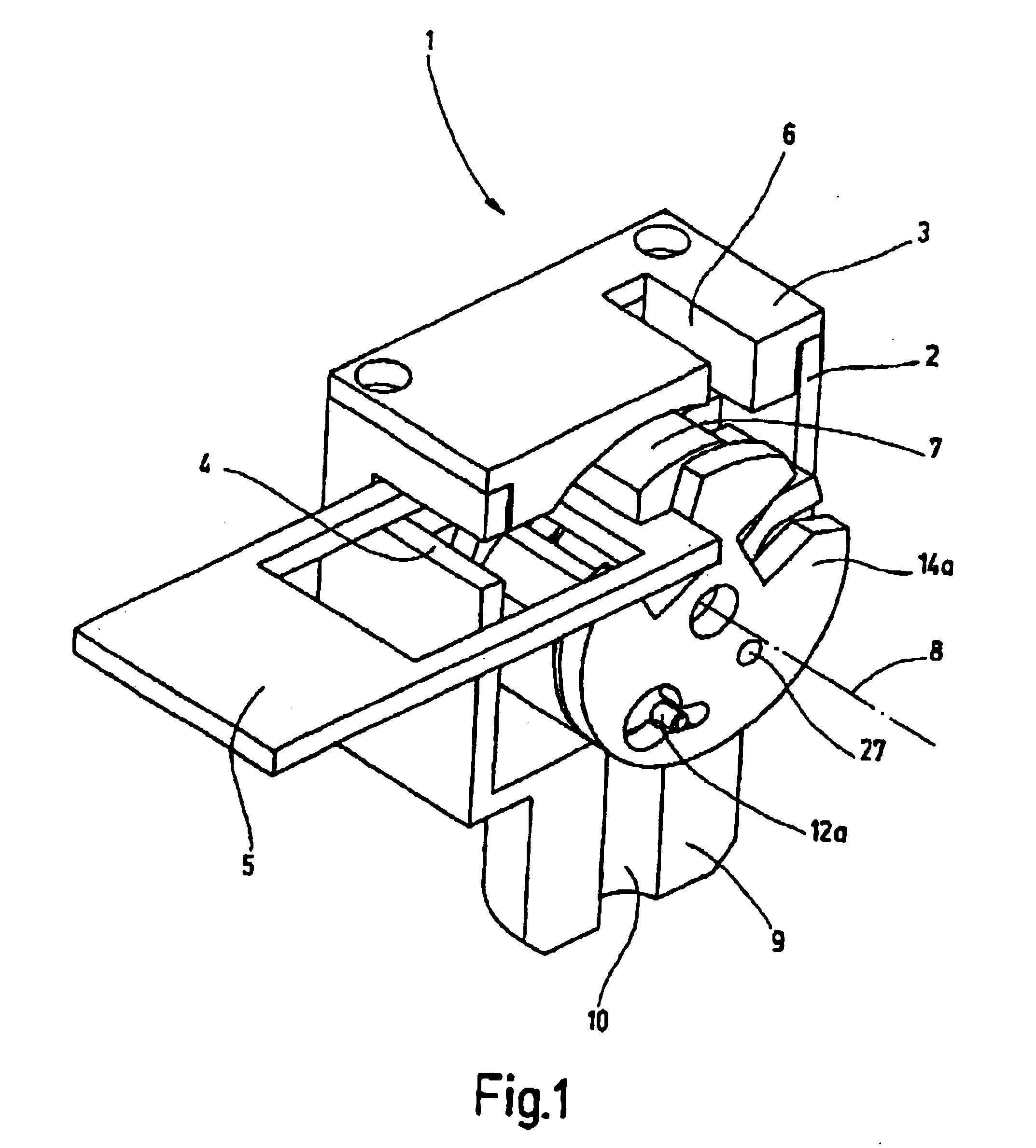
FIG. 1 illustrates a safety switch 1 according to an embodiment of the present invention, with a housing having a housing top part 2 and a housing cover 3. Cover 3 may be slip-on mounted on the housing top part 2 and fastened to it, for example, by screws. The housing top part 2 has a first insertion slot 4 for the actuator 5. The housing cover 3 has a second insertion slot 6 for the actuator 5. The directions of insertion predetermined by the two insertion slots 4 and 6 enclose or are spaced by an angle of more or less 90°.

A switching disk 7 is mounted in the housing top part 2 for rotation about an axis 8. When the actuator 5 is inserted into at least one of the two insertion slots 4, 6 the switching disk 7 illustrated in FIG. 1 is rotated clockwise causing a switching rod 28 (not shown in FIG. 1) to be displaced axially so that an electric connection is made. The guide of the switching rod 28 and the electric contact elements are mounted in a switch housing component (not shown in F


PUM


Abstract

A device switches an electrical connection in accordance with the condition of a device to be monitored, especially to a safety switch (1) for a protective device. The safety switch includes a housing (2,3) in which a switch disk (7) is mounted for rotation about an axis (8). An actuator (5) can be inserted for triggering the switching process. A latching device blocks the switch disk (7). The latching device has a latching element (12a, 12b) guided in the switch disk (7) and movable against the effect of a first energy accumulator (11). In a position in which it blocks the switch disk (7), the latching element (12a, 12b) engages an associated recess (13a, 13b) in the housing (2, 3). A rotatable release element (14a, 14b) disposed beside the switch disk (7), is rotatable relative to the switch disk (7) when the actuator (5) is inserted. When the release element (14a, 14b) is rotated, the latching element (12a, 12B) is slid back parallel to the axis (8) into the switch disk (7) against the effect of the first energy accumulator (11), thereby placing it in a release position.

Description


Claims


Application Information

Patent Timeline
Owner EUCHNER GMBH & CO KG
Why Eureka
Try Eureka