Cable connector assembly having pull tab

a connector and pull tab technology, applied in the direction of electrical equipment, connection, coupling device connection, etc., can solve the problems of conductors standing a good chance of being divorced from contact modules, affecting signal transmission, and only loosening screw connections by operators, etc., to achieve convenient separation

Inactive Publication Date: 2005-03-15
HON HAI PRECISION IND CO LTD
View PDF9 Cites 33 Cited by
  • Summary
  • Abstract
  • Description
  • Claims
  • Application Information

AI Technical Summary

Benefits of technology

The technical effect of this patented design is that it makes it easier for cables to be connected without having to use an adapter.

Problems solved by technology

This patent describes a problem where operators cannot easily separate a cable connector assembly from another due to their limited ability to use their hands alone.

Method used


Image

  • Cable connector assembly having pull tab
  • Cable connector assembly having pull tab
  • Cable connector assembly having pull tab

Examples


Embodiment Construction

Reference will now be made in detail to the preferred embodiment of the present invention.

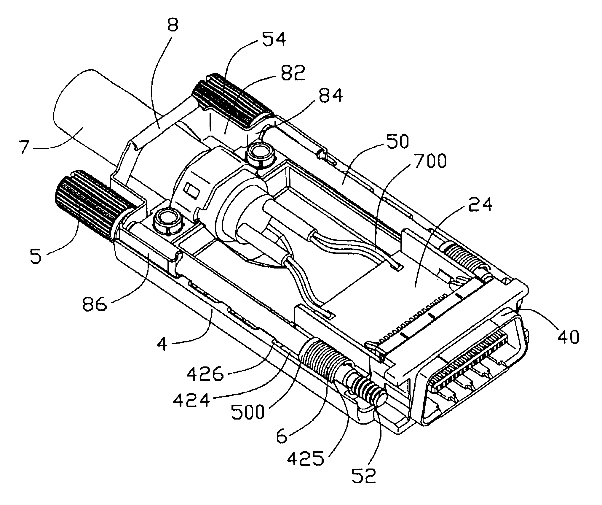
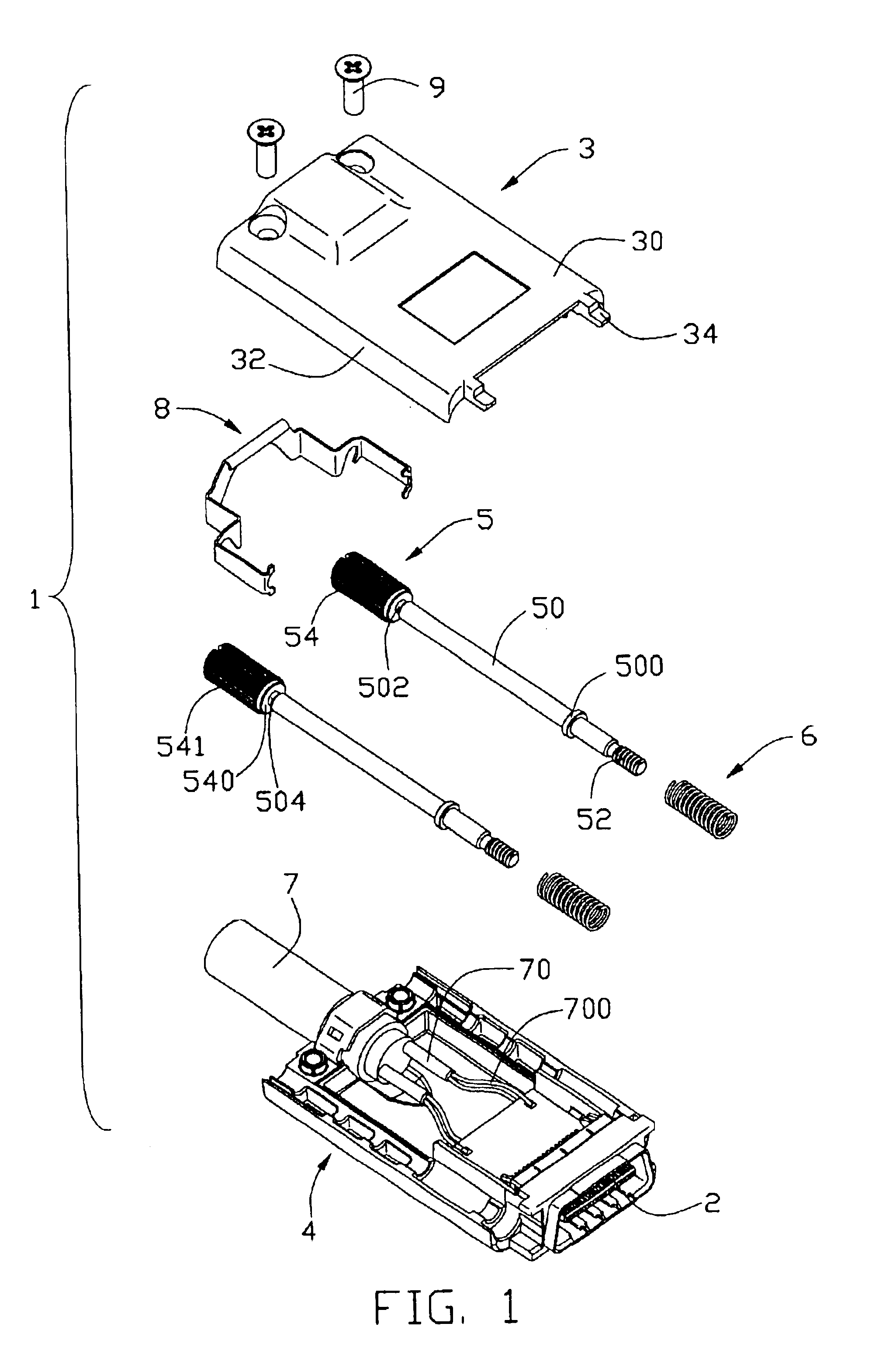
Referring to FIG. 1, a cable connector assembly 1 in accordance with the present invention comprises a contact module 2, an upper die cast cover-half 3, a lower die cast cover-half 4, a pair of fastening members 5, a pair of spring members 6, an electrical cable 7, a pull tab 8 and a pair of screws 9.

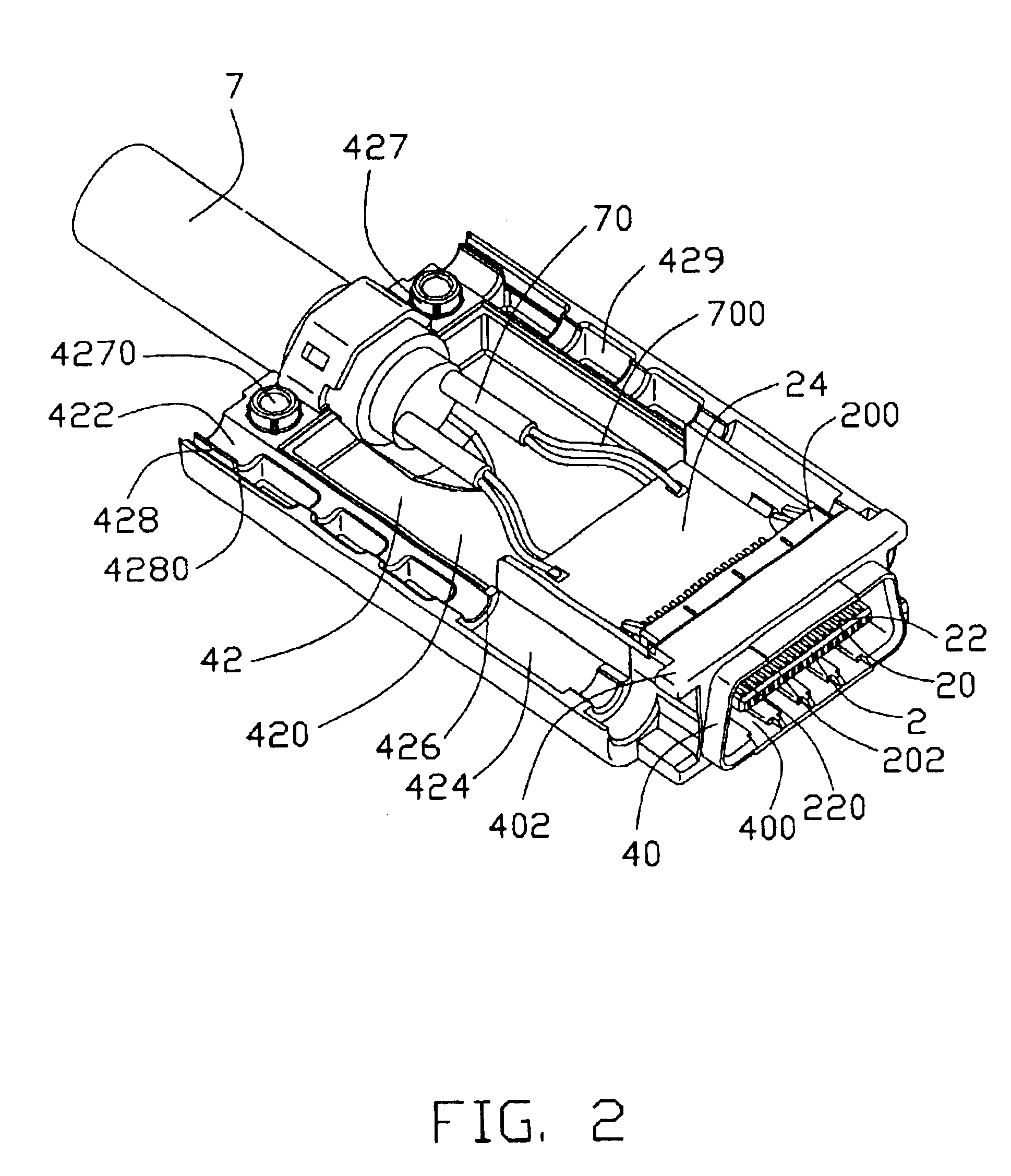
Referring to FIGS. 1-3, the contact module 2 comprises an insulative housing 20, a plurality of contacts 22 and a printed circuit board 24. The insulative housing 20 comprises a base portion 200, a tongue portion 202 extending forwardly from the base portion 200 and a plurality of passageways (not labeled) extending from the tongue portion 202 through the base portion 200.

The contacts 22 are received in the passageways of the insulative housing 20. Each contact 22 comprises a contacting portion 220 retained in the tongue portion 202 for contacting with a complementary connector (not shown) and a conne


PUM


Abstract

A cable connector assembly (1) includes a first and a second cover-halves (3, 4) joined together to define a front and a second end, an insulative housing (20) retained in the front end of the first and the second cover-halves, a number of contacts (22) retained in the insulative housing, a cable (7) electrically connected with the contacts, a fastening member (5) and a pull tab (8). A first passage (45) extends through the front and the rear ends. The fastening member is movably and rotatably received in the first passage and includes a medial portion (50), a threaded portion (52) extending from the medial portion, and an operating portion (54) extending from the medial portion opposite to the threaded portion. The pull tab is movably mounted to the rear end of the cover-halves and is secured to the fastening member for separating the cable connector assembly from the complementary connector.

Description


Claims


Application Information

Patent Timeline
Owner HON HAI PRECISION IND CO LTD
Why Eureka
Try Eureka