Method and apparatus for reducing self-interference in a mobile network

a mobile network and self-interference technology, applied in the field of mobile communication systems, can solve the problems of self-interference, simple solution that does not work well in the network with airborne nodes, and frequency reuse methods that work well in the terrestrial environment will not work well in the airborne rf environment, so as to achieve the effect of reducing interferen

Active Publication Date: 2005-09-20
THE BOEING CO
View PDF13 Cites 21 Cited by
  • Summary
  • Abstract
  • Description
  • Claims
  • Application Information

AI Technical Summary

Benefits of technology

This patented technology helps reduce interruptions when two devices want communication on different networks simultaneously without causing any problems or compromising their performance. It involves measuring angles between signals sent by both parties' terminals before they are connected together through some type of connection called wireline connections. By comparing these measurements against predetermined thresholds, it can determine if there will be more signal loss than expected during transmission. Based on this measurement, new nodes may join up quickly instead of waiting until all other users have finished speaking again after being joined.

Problems solved by technology

Technological Problem: Self-Interference Compensation (SIC), particularly in Airbornet Networking Systems (ANS), affects signal quality due to variations in environmental factors including temperature fluctuations from altitude change caused by weather patterns. These issues lead to reduced reliability and performance in LTE systems compared to traditional land based technologies.

Method used


Image

  • Method and apparatus for reducing self-interference in a mobile network
  • Method and apparatus for reducing self-interference in a mobile network
  • Method and apparatus for reducing self-interference in a mobile network

Examples


Embodiment Construction

[0029]The following description of the preferred embodiment(s) is merely exemplary in nature and is in no way intended to limit the invention, its application, or uses.

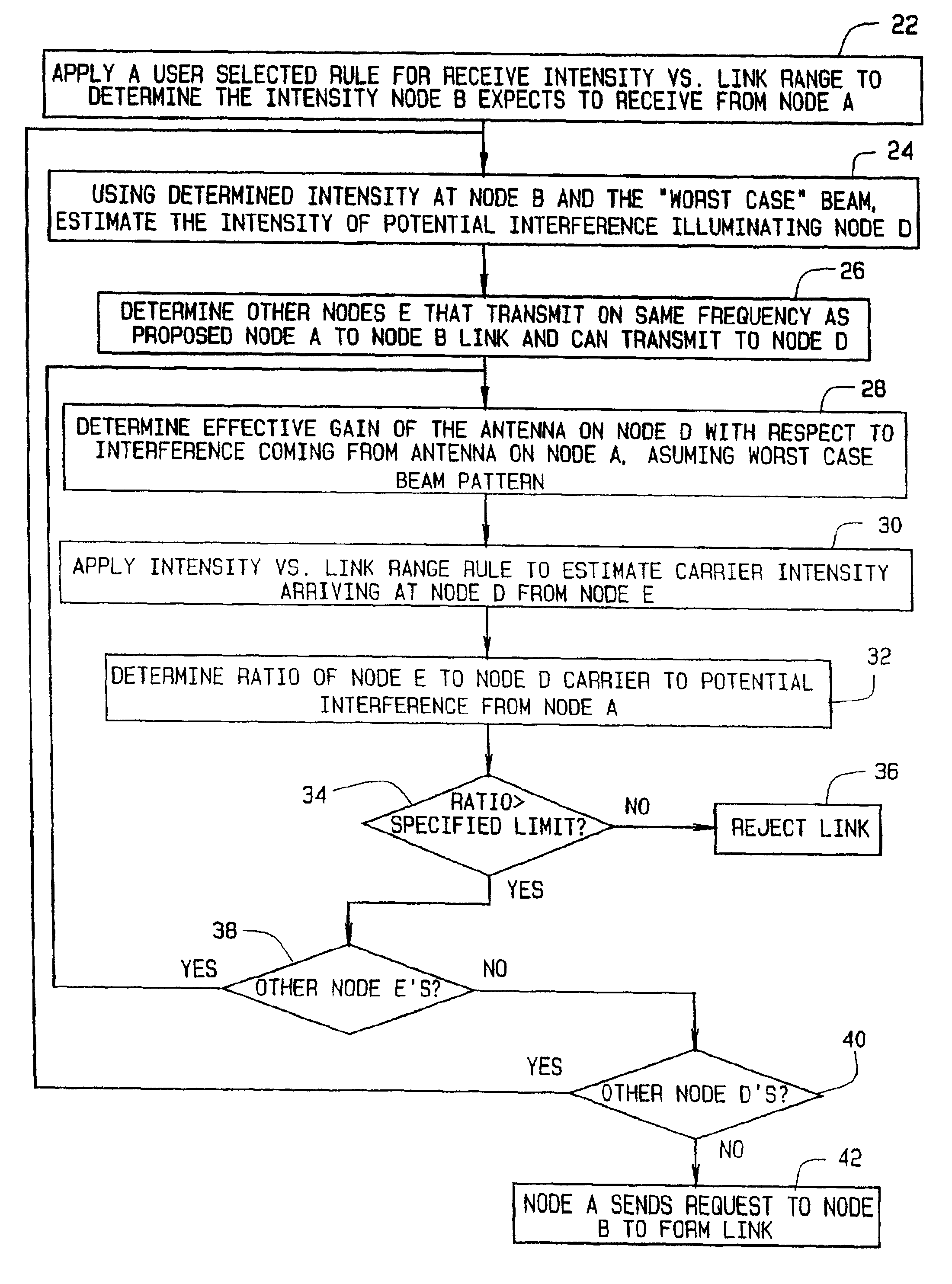
[0030]As used herein, the designations “node A” and “node B” refer to nodes in the process of establishing a link. (A “link,” as used herein, is a wireless communication path.) The designation “node C” refers to a node other than node A in communication with, or capable of communicating with node B. The designations “node D” and “node E” refer to two nodes other than nodes A and B in communication with each other, or capable of linking with one another, but not necessarily with node A or with node B. From the standpoint of node A and node B in a network, there may be zero, one, or a plurality of nodes C, zero, one or a plurality of nodes D, and zero, one, or a plurality of nodes E. In addition, there may be zero, one, or a plurality of nodes E for any particular node D, as any particular node D may be in communication wi


PUM


Abstract

A method for reducing interference in a mobile network in which a node A proposes a wireless link with node B. The method includes: (a) determining an angle between an incoming link from a node C to node B and the proposed node A to node B link, wherein the incoming link and the proposed link utilize the same frequency; (b) utilizing a nominal center of a beam of the proposed link, estimate an effective gain at node B to admit interference from the direction of node A into the incoming link from node C; (c) estimating a carrier intensity arriving at node B from node C; (d) determining a ratio of arriving node C to node B carrier to potential interference from the proposed node A to node B link; and (e) conditioning establishment of the proposed node A to node B link upon the determined ratio.

Description


Claims


Application Information

Patent Timeline
Owner THE BOEING CO
Why Eureka
Try Eureka